Thermal Imagers
SEG12
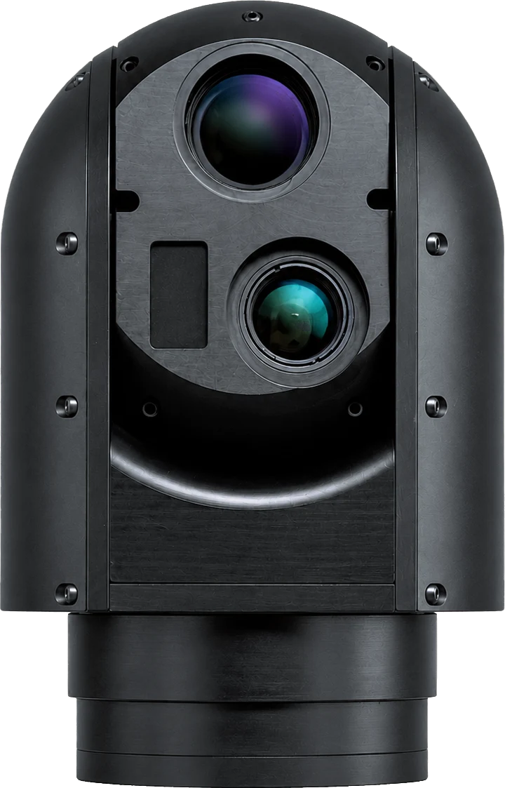
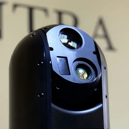
Multi Channel (EO-LWIR-LRF) Stabilised Gimbal System
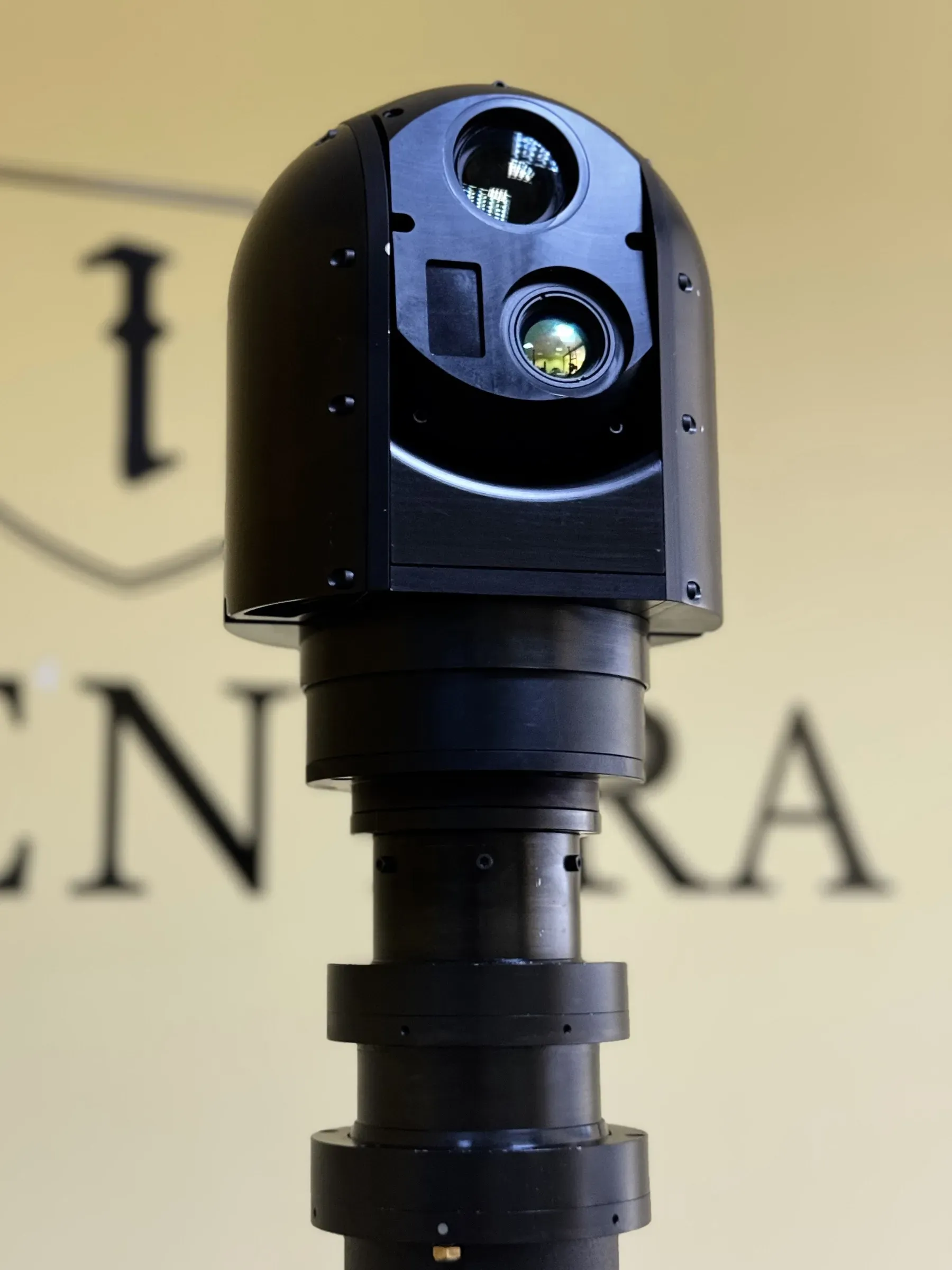
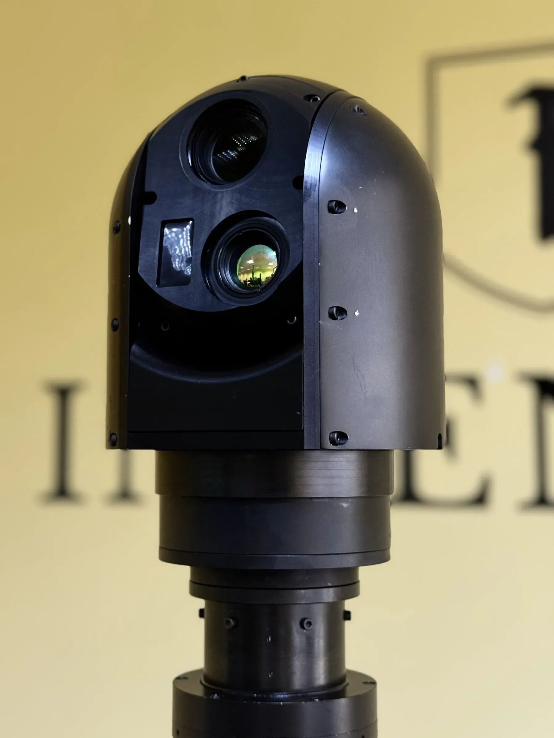
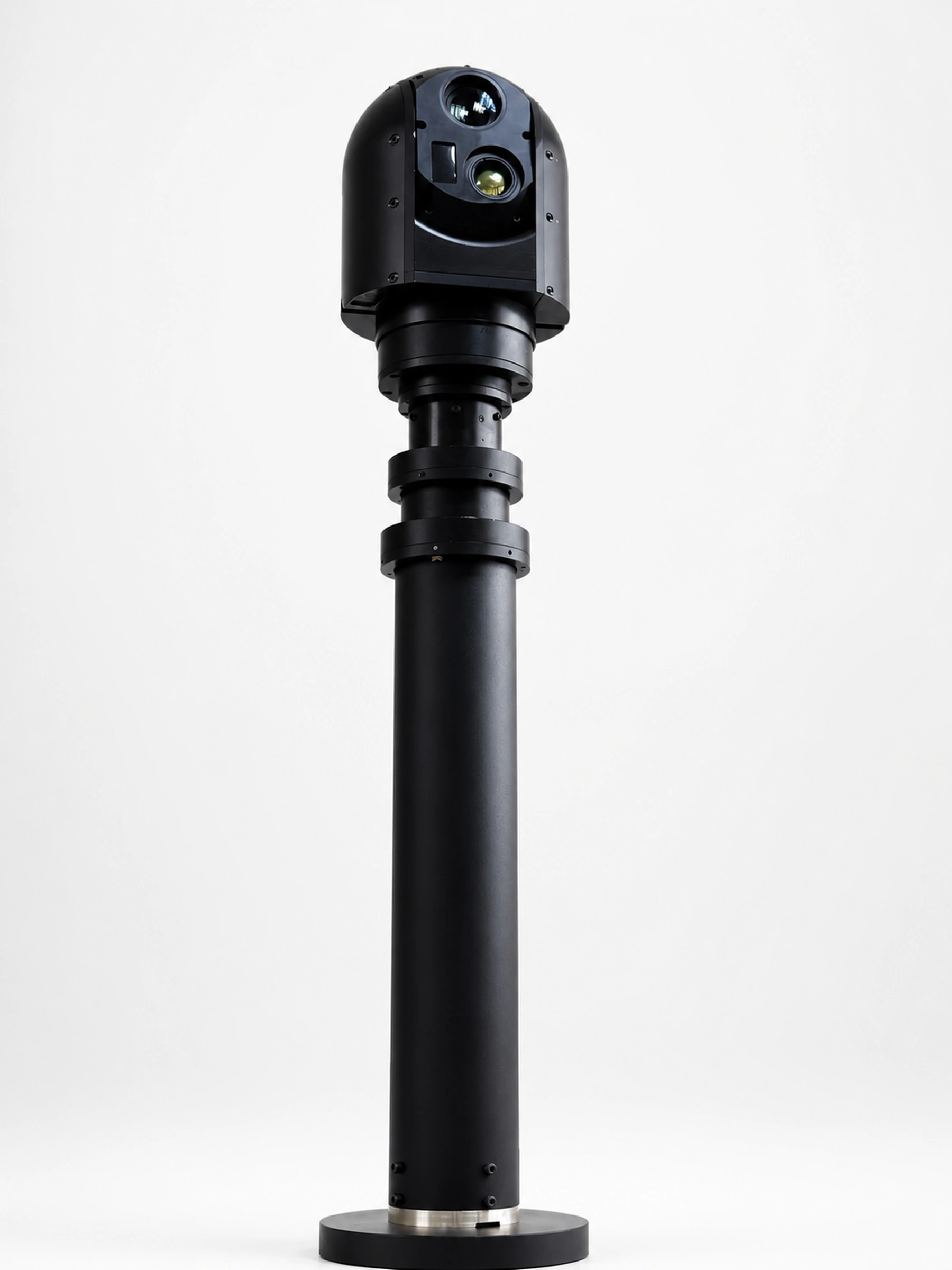
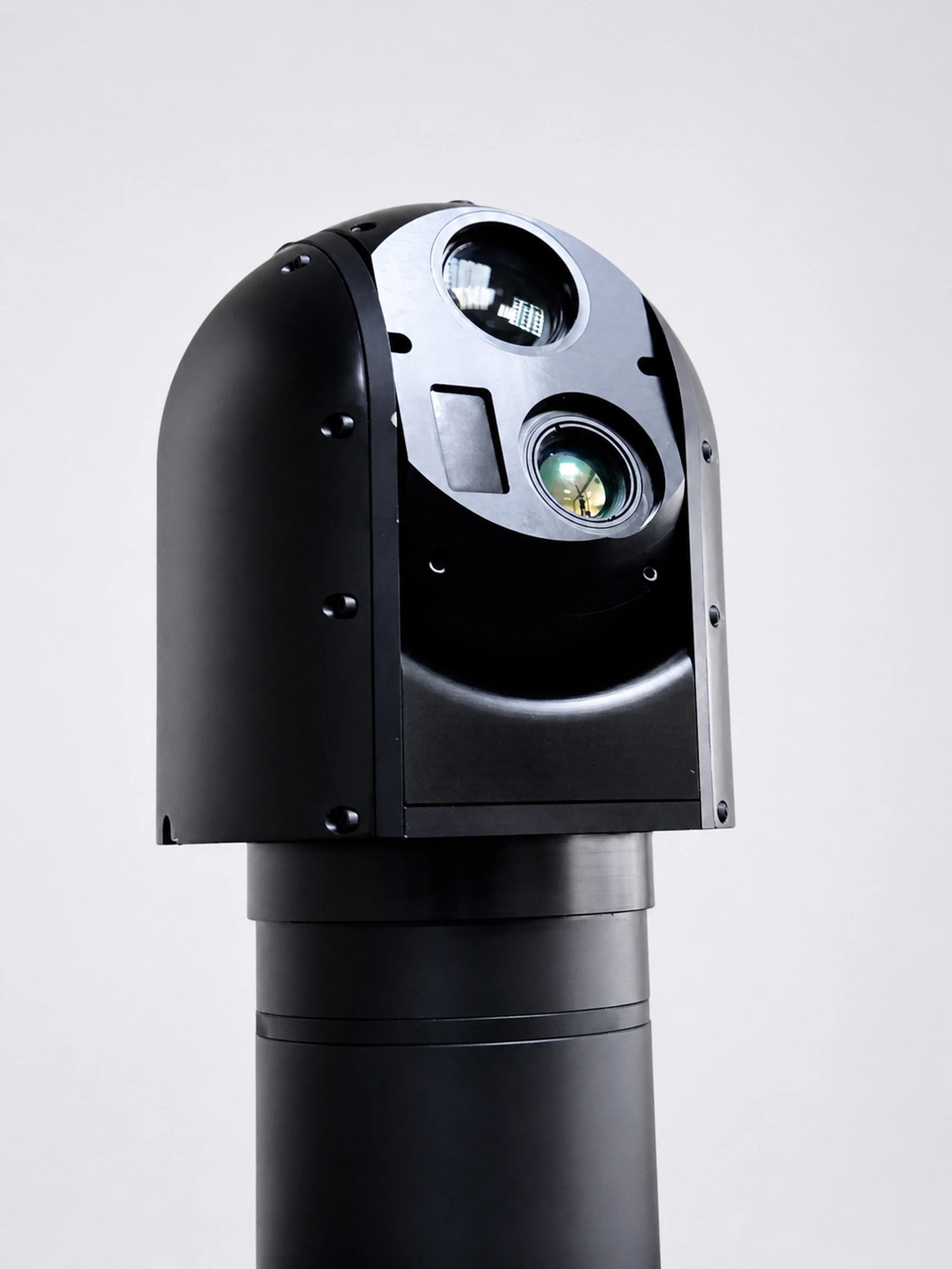
Compact triple-channel gimbal adding a 5000 m laser rangefinder to the 30x EO and 640x512 LWIR channels, with digital image blending on one video downlink.
- LWIR
- 640 × 512 px
- 5-5.000 m
- 1.920 × 1.080 px
- Resolution
- 640 × 512 px
- Detector
- 5-5.000 m
- Ranging Scope
Highlights
01Triple channel
EO, thermal and laser ranging on one downlink
The EO, LWIR and laser rangefinder channels acquire data and take commands at the same time. A 5000 m rangefinder turns an observation into a coordinate.
- 1500 nm rangefinder, 5 to 5000 m
- Optional laser pointer on the same head
02Image blending
Thermal and colour combined in one video channel
Full digital blending merges the thermal and colour images before they leave the unit, so a single downlink carries the combined view rather than two feeds the operator must reconcile.
- Uncooled LWIR keeps MTBF high and ownership cost low
- Onboard video compression for narrow links
Gallery
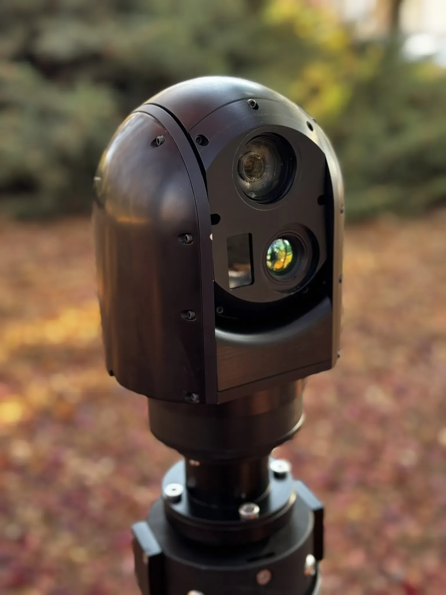
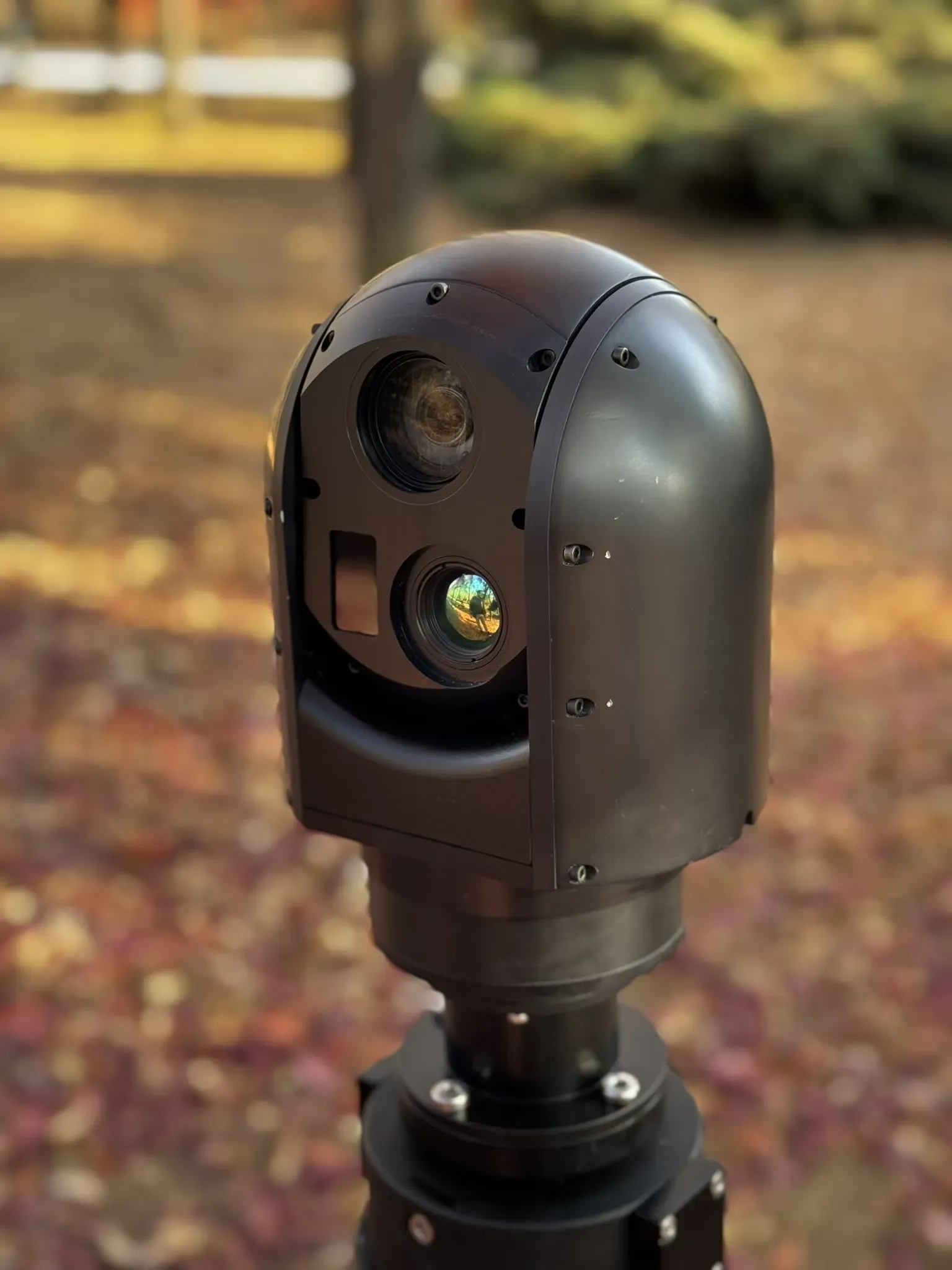
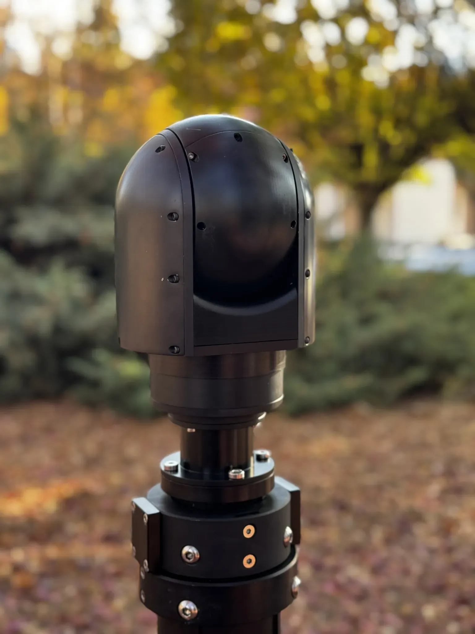
Select a frame to open it at full size.
Options
- LCKTLens Cleaning Kitordered separately
- LG##Label LanguageEN English, FR French, TR Turkish, AR Arabic, ES Spanish
Specifications
| Pan and Tilt – Nominal Speed | 180 °/s |
|---|---|
| Pan – Axis Range | 360° continuous |
| Tilt – Axis Range | ±45° |
| Weight | 4,6 kg |
| Spectral Band | LWIR |
|---|---|
| Detector | 640 × 512 px |
| Pixel Size | 12 µm |
| NETD | 50 mK |
| MRTD | 500 mK |
| Thermal Lens | 25 mm |
| Thermal Optical Zoom | None |
| Thermal Horizontal Field of View | 17,7° |
| Thermal Digital Zoom | 12× |
| Resolution | 1.920 × 1.080 px |
|---|---|
| EO Optical Zoom | 30× |
| EO Horizontal Field of View | 63,7-2,3° |
| EO Digital Zoom | 12× |
| Minimum Illumination – High Sensitivity | 0,01 lx |
| Focusing System | Automatic |
| Ranging Scope | 5-5.000 m |
|---|---|
| Laser Wavelength | 1,5 µm |
| Laser Type | Eye-safe |
| Tracker Stabilisation | Two-axis IMU and encoder based dual-loop |
|---|---|
| Data Refresh Rate | 25 Hz |
| Output Lag | 100 ms |
| Target Size | 16 × 16-128 × 128 px |
| Power Consumption (Max) | 150 W |
|---|---|
| Operating Voltage | 18-32 VDC |
| Communication Interface | RS-422 |
| Communication Interface (Optional) | Ethernet |
| Connector Type | MIL-DTL-38999 |
| Video Output 1 | HD-SDI |
| Video Output 2 | Ethernet |
| Diameter | 160 mm |
|---|---|
| Height | 256 mm |
| Material – Main Body | Aluminium 6061-T6 |
| Surface Finish | Electrostatic Powder Coating |
| Standard Colour | RAL 9005 Matte Black |
| Installation Manual | 1 × Installation Manual |
|---|
| Environmental Standard | MIL-STD-810G |
|---|---|
| High Temperature – Operational | Mtd. 501.5, Proc. II, +60 °C |
| High Temperature – Storage | Mtd. 501.5, Proc. I, +70 °C |
| Low Temperature – Operational | Mtd. 502.5, Proc. II, -32 °C |
| Low Temperature – Storage | Mtd. 502.5, Proc. I, -40 °C |
| Low Pressure – Operational | Mtd. 500.5, Proc. II, 10.500 ft |
| Low Pressure – Storage | Mtd. 500.5, Proc. I, 37.000 ft |
| Rain | Mtd. 506.5, Proc. I, 1,7 mm/min, 18 m/s wind, 30 min per exposed face |
| Salt Fog | Mtd. 509.5, 5 % NaCl, 2 cycles of 24 h fog and 24 h drying |
| Blowing Dust | Mtd. 510.5, Proc. I |
| Blowing Sand | Mtd. 510.5, Proc. II |
| Vibration | Mtd. 514.6, Proc. I, Cat. 4 – Secured Cargo, Fig. 514.6C-3 |
| Shock | Mtd. 516.6, Proc. I, 20 g, 11 ms, 3 shocks per direction in 3 axes |
| EMI/EMC Standard | MIL-STD-461G |
|---|---|
| CE102 | Power Leads, 10 kHz – 10 MHz |
| CS101 | Power Leads, 30 Hz – 150 kHz |
| CS114 | Bulk Cable Injection, 10 kHz – 200 MHz |
| CS115 | Bulk Cable Injection, Impulse Excitation |
| CS116 | Damped Sinusoidal Transients, 10 kHz – 100 MHz |
| CS118 | Personnel Borne Electrostatic Discharge |
| RE102 | Electric Field, 10 kHz – 18 GHz |
| RS103 | Electric Field, 2 MHz – 18 GHz |
Documents
- DatasheetDownloadable — PDF, 222 KB
- User ManualOn Request
- 3D Model (STEP)On Request
- Mechanical Interface Control DocumentOn Request
- MIL-STD-810G Environmental Qualification ReportOn Request
- Electrical Interface Control DocumentOn Request
- Software Interface Control DocumentOn Request
- MIL-STD-461G EMI/EMC Test ReportOn Request