A Precise Map Pin Can Share the Wrong Reference
A reservoir inspection example shows how bearing and range become a map position, why shared references can conceal offsets, and how correlation and two-dimensional coverage change the uncertainty region.
Download the article (PDF)PDF · 1004 KB
Begin with the physical feature, then the geometry
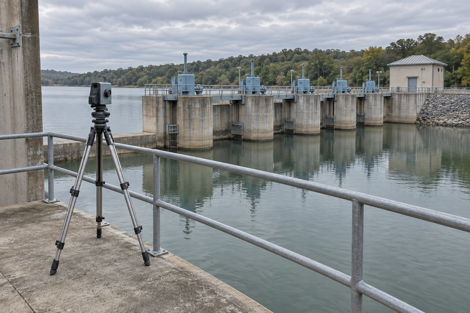
A water-utility inspection team needs to attach an observation to one outlet gate among several similar structures. A crisp map pin is useful only if it identifies the intended physical feature. Decide whether the recorded point means the hinge, valve housing or structure centre. A coordinate calculation cannot repair ambiguity about what was observed.
For a short-range calculation, use a local east–north plane. The asset position equals the sensor’s surveyed origin plus the measured displacement. With horizontal distance D and bearing a clockwise from north, the displacement is D sin(a) east and D cos(a) north. If the instrument reports slant distance R and elevation e, first use D = R cos(e).
That geometry explains why a single distance-error number hides information. A small range error moves the estimate mainly along the viewing direction. A small bearing error moves it sideways by approximately D × angular error, with the angle expressed in radians. Rotating the view rotates those directions on the map.
Take a planning example with a fixed sensor and fixed feature, 500 m apart horizontally, looking north at equal height. Assume a bearing standard uncertainty of 0.80 mrad, or 0.00080 rad. Its sideways contribution is 500 m × 0.00080 = 0.40 m. At 1,500 m, the same angular uncertainty contributes 1.20 m.
These are local geometric calculations, not product ratings. They omit curvature, atmospheric effects and height uncertainty; a wider-area or inclined-view solution needs the corresponding three-dimensional model. Even here, the 0.40 m term is only the uncertainty of a displacement. The sensor origin and its relationship to the map still have to be included.
Range, bearing and origin uncertainty affect different parts of the mapped position.
Two agreeing records can share the same offset
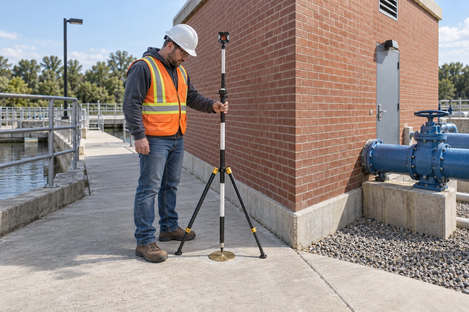
A coordinate reference system, or CRS, tells software how coordinate values relate to physical locations. Record the exact system, units and axis order. For a projected map, also preserve the conversion between the measured bearing reference and grid direction. Assigning a different CRS label to unchanged numbers is not a coordinate transformation. OGC’s coordinate-reference standard describes the system and operation separately.
Keep two kinds of time distinct. Observation time associates the image, range and sensor pose with the same event. Coordinate epoch states when coordinates apply within a dynamic reference frame. A current image can be paired with coordinates expressed at an earlier epoch; that is legitimate if the relationship is defined. OGC’s CRS guidance, section 6.2.2 explains the ambiguity when an applicable coordinate epoch is missing.
Height needs its own reference. Height above a reference ellipsoid and height relative to a gravity-based vertical datum are different quantities. Preserve the vertical datum and any geoid model used to convert between them, as described in USGS datum-documentation guidance.
Now suppose both the sensor origin and the utility’s asset map inherited an unnoticed eastward translation from the same site survey. Their positions may agree beautifully. Subtracting one from the other cancels that shared translation, while both remain displaced against an independently established reference.
This is a consequence of the measurement model: errors b + a and b + c differ by a − c. A good relative comparison therefore does not establish a good absolute location. Check a stable feature whose reference was established independently of the suspected shared survey, and account for that check’s own uncertainty.
Independence belongs to the reference history, not to the number of displayed records.
The missing term in a root-sum-square budget
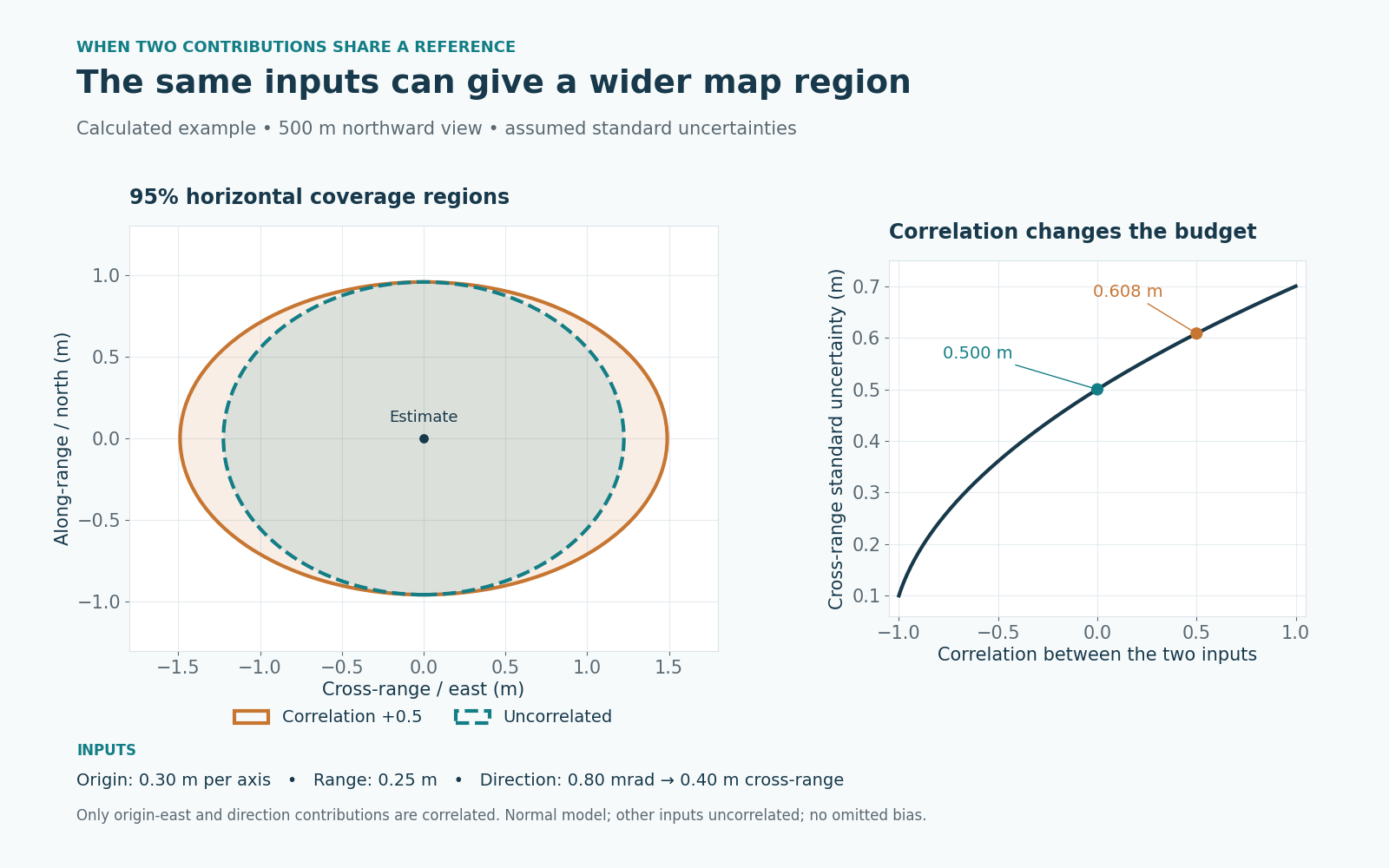
In the same northward 500 m example, assume standard uncertainties of 0.30 m in each origin coordinate, 0.25 m in horizontal range and 0.80 mrad in bearing. Standard uncertainty is an estimated standard deviation; converting a maximum-error limit into one requires justification.
With uncorrelated inputs, the eastward result combines origin and bearing:
u(east) = √(0.30² + 0.40²) = 0.50 m.
The northward result combines origin and range:
u(north) = √(0.30² + 0.25²) = 0.391 m.
Origin and orientation may share a survey adjustment. For correlated additive contributions A and B, include covariance:
u² = uA² + uB² + 2ρuAuB.
Here ρ is their correlation coefficient. NIST’s uncertainty-propagation guidance includes this covariance term. Zero correlation removes it; positive correlation increases the uncertainty of a sum. A difference reverses the covariance term, so the measurement equation’s signs matter.
For an assumed ρ = +0.5 between origin-east and bearing contributions, u(east) = √(0.09 + 0.16 + 0.12) = 0.608 m. Keep the other inputs uncorrelated. The northward result stays 0.391 m.
This example correlates two inputs to the east coordinate; it does not correlate the final east and north coordinates. More general geometries can do both.
A shared reference changes the mathematics even when every individual uncertainty stays the same.
State what the region covers before judging the pin
Do not choose correlation merely to make the budget fit. Request the adjustment covariance or model the shared reference explicitly. Correct established offsets, retain their residual uncertainty, and include each physical source once.
A standard uncertainty is not a radius that automatically contains 95% of possible positions. Even a correct combination needs a coverage statement. For one normally distributed quantity, approximately twice its standard uncertainty gives a 95% interval under suitable assumptions. NIST’s coverage guidance makes those conditions explicit.
A horizontal location contains two quantities together. Under a bivariate normal model with adequately known covariance, a 95% ellipse uses a factor of about 2.448 along its principal uncertainty directions. A factor of 2 encloses only about 86.5% in that two-dimensional model. JCGM 102:2011, section 6.5.2 gives the joint-coverage construction.
For the correlated-input example, the 95% ellipse has half-widths of approximately 1.49 m east–west and 0.956 m north–south. With uncorrelated inputs, the east–west half-width would be 1.22 m. These are distances from the centre, not full widths. No extra displayed decimal places change either region.
The result depends on the stated model. An omitted map offset can put the whole ellipse in the wrong place. Heavy-tailed errors, weakly estimated covariance or strongly nonlinear geometry require a more suitable coverage calculation. Reporting a normal ellipse does not establish that those conditions hold.
For the reservoir record, request four connected pieces of evidence:
| Evidence | What it resolves |
|---|---|
| Feature photograph and physical point definition | Which part of which gate was observed |
| Original coordinates, CRS and applicable epoch | How the point relates to the site map |
| Matched observation time, range and pose | Whether the inputs describe the same event |
| Covariance, coverage method and independent check | What uncertainty remains and what was tested |
If the region overlaps competing asset features, collect stronger identification evidence or improve the limiting measurement before attaching the observation to one asset. The decision is about distinguishing physical features, not making the pin look precise.
A usable location couples a defined feature with reference, timing and an explained coverage region.
Download the full article (PDF)
Related reading: Why a Repeatable Positioner Can Still Point Wrong · The Newest Angle Can Belong to the Wrong Image
Sources and further reading
- From Bearing and Range to a Grid Reference: the Target Location Error Budget
- Combining uncertainty components
- Expanded uncertainty and coverage factors
- JCGM 102:2011 — Extension to any number of output quantities
- Geographic information — Well-known text representation of coordinate reference systems
- OGC API — Features — Part 2: Coordinate Reference Systems by Reference corrigendum
- Guidance on Use and Documentation of Horizontal and Vertical Datums in USGS Publication Series Information Products