The Newest Angle Can Belong to the Wrong Image
An angle can arrive recently yet describe a different moment from the saved image. Commission the full association: define timestamp events, compare clocks, interpolate across angle wrap, and verify the result with an independent timing witness.
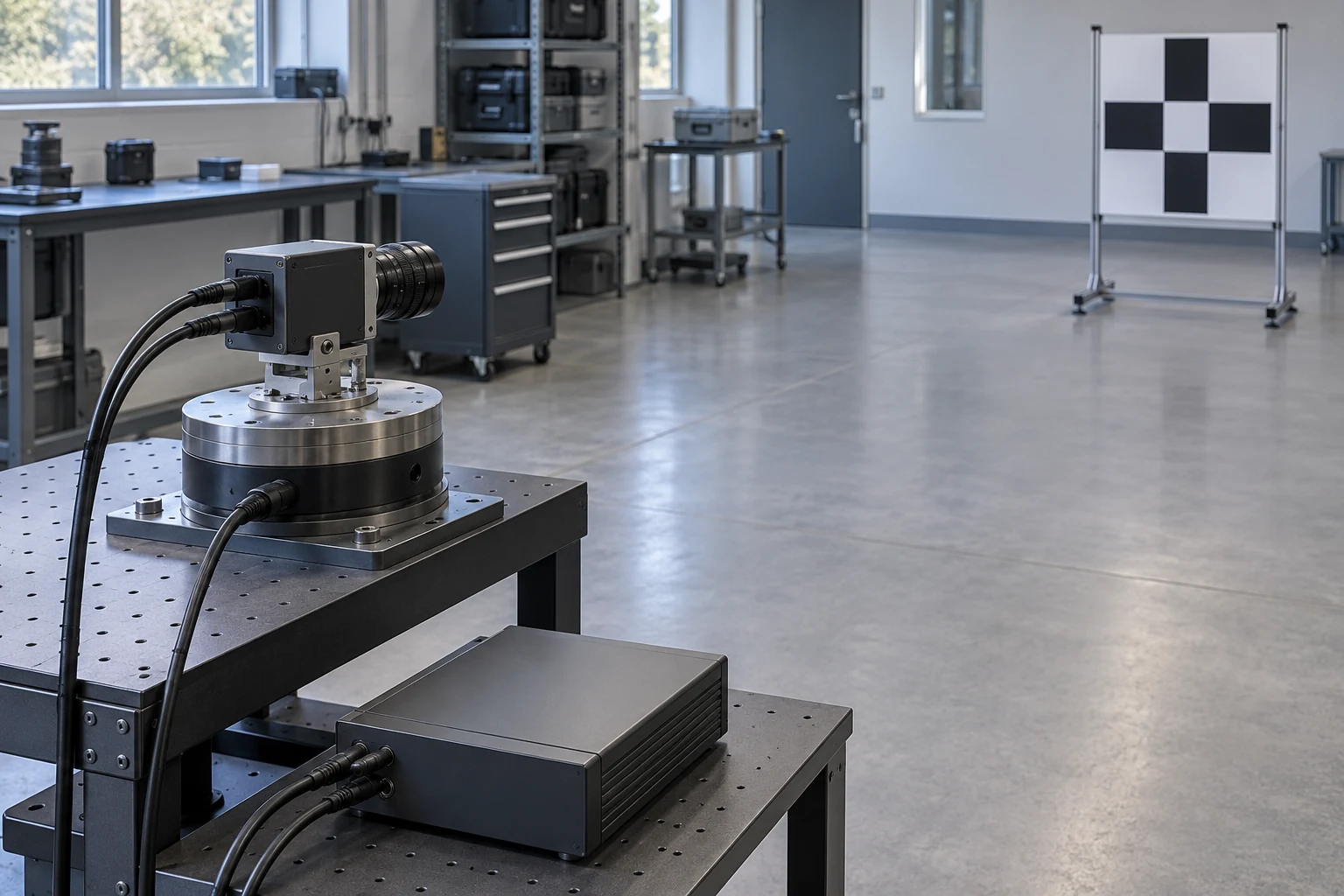
- Rated Payload
- 12 kg
- Accuracy
- 0,056°
- Axis Resolution
- 0,0056°
- Weight
- 2,9 ± 0,1 kg
First ask what the timestamp describes
A camera sweeps across a fixed inspection marker. The recorder saves an image and attaches the latest angle message. Both records are valid, yet the caption can point somewhere the camera had already passed. “Latest” describes the recorder’s knowledge; it does not identify the angle during exposure.
Begin with three separate events: the sensor samples an angle, the camera exposes an image, and the receiving software accepts their messages. Keep each original timestamp, its clock identity, its event definition and its record identifier. Preserve arrival time separately so transport delay can still be investigated.
This distinction exists even inside familiar software interfaces. Linux camera buffers distinguish the clock used from the point in the frame when the timestamp was taken. Network hardware receipt and receipt in the operating system are also different timestamp locations. Neither is automatically the time a remote angle was measured. Camera buffer definitions; network timestamp locations.
Two clocks must also be comparable. Record their time origin, units, conversion to the common timeline and measured agreement. NIST defines synchronized clocks through an uncertainty for the same event. A synchronization status alone does not establish where either sensor generated its timestamp. NIST timing terminology.
For an Inventra S³ PEG03 integration, request the software and electrical interface documents for the supplied configuration. Its published page offers those documents on request; it does not establish sample timestamp semantics or a synchronization protocol. The method below requires those answers, the camera exposure definition and the inspection’s allowable angle-association error. PEG03 documentation.
Identify the physical event behind every timestamp before comparing numbers.
Calculate the cost of choosing the latest message
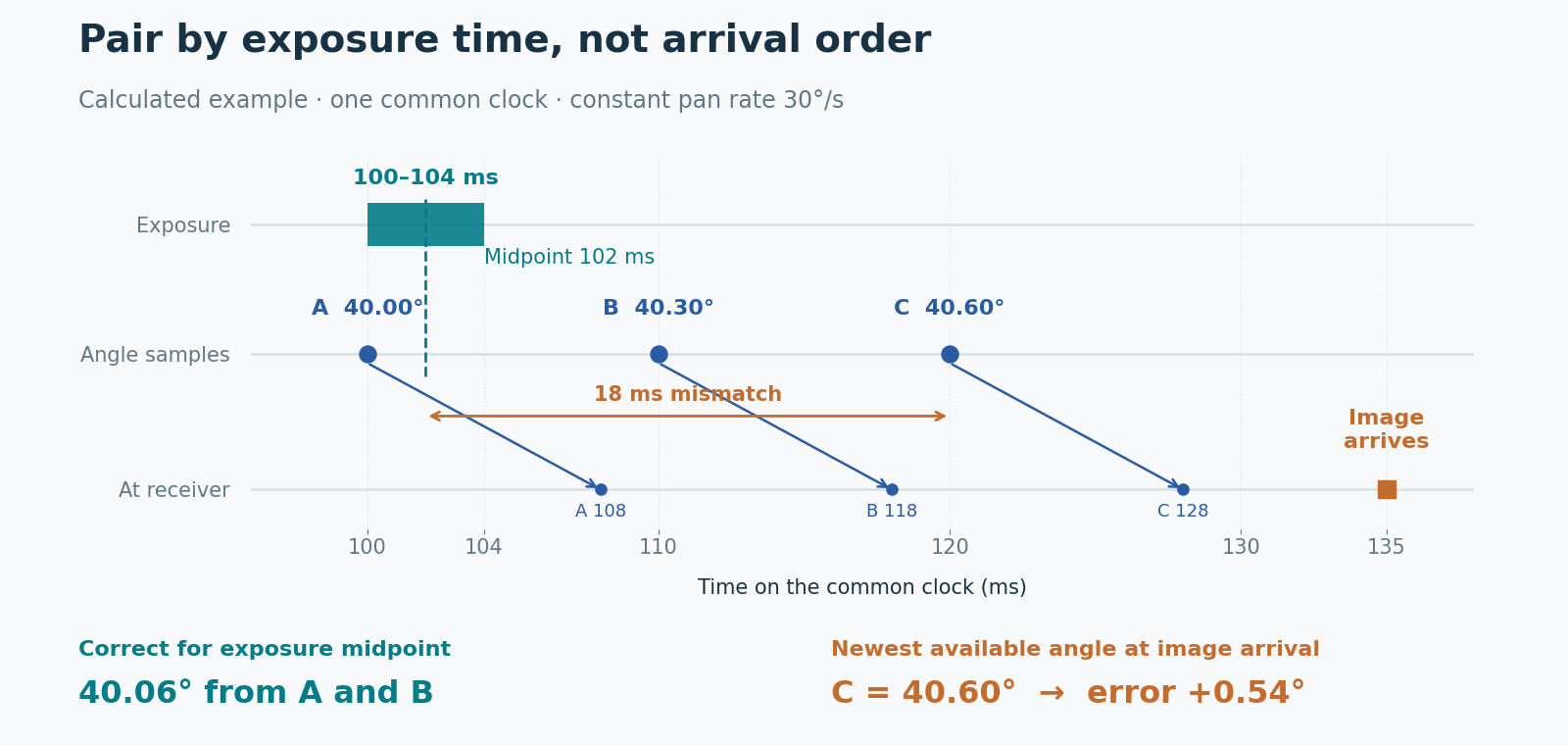
Consider a calculated commissioning example with one common clock, constant pan at 30°/s, and a global exposure from 100 to 104 ms. The exposure midpoint is 102 ms. The assumptions describe a test case, not a product speed or latency rating.
Angle samples A, B and C occur at 100, 110 and 120 ms, with values 40.00°, 40.30° and 40.60°. Each message arrives 8 ms later. The image arrives at 135 ms. At that moment C is the newest angle available, but it was measured 18 ms after the exposure midpoint.
The angular mismatch is speed multiplied by time offset:
30°/s × 0.018 s = 0.54°.
Using C labels the image 40.60°. Interpolating between A and B at 102 ms instead gives 40.00° + 0.2 × 0.30° = 40.06°. Notice that the 8 ms message delay is not the 18 ms association error. Comparing the two delivery times would answer another question entirely.
The exposure is an interval, too. Pan changes by 0.12° during these 4 ms. With constant speed and uniform integration, the midpoint represents the mean angle, but it cannot describe every instant within the image. Preserve exposure duration along with the chosen reference time.
If the camera timestamp marks exposure start, add half the known duration for this midpoint convention. A timestamp marking receipt of the final pixel needs a different, verified mapping. Linux explicitly distinguishes those events. Other shutter modes need their own validated exposure model before this calculation applies. Frame timestamp sources.
In this example, the most recent available angle is 0.54° ahead of the exposure midpoint.
Preserve angle history across zero
Store a short angle history in measurement-time order. For each image, convert its exposure reference to that same clock, then find valid samples immediately before and after it. Interpolate only across a gap and motion regime that the commissioning evidence supports. If the later sample is unavailable, wait within the recording deadline or mark the association unavailable; extrapolation needs a separate error bound.
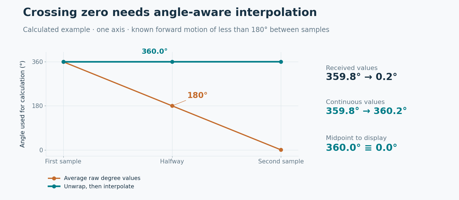
Resolve angle wrapping before interpolation. Suppose consecutive samples are 359.8° and 0.2°, with known small forward motion. Averaging the raw values gives 180°, the opposite direction. Treat the second sample as 360.2° instead: the halfway angle is 360.0°, displayed as 0.0°. Keep a continuous angle internally and apply the display range afterward.
That choice needs evidence. If motion could reach half a turn between samples, the shortest path can be ambiguous; beyond half a turn it may lose a revolution. Use a documented revolution count or another unambiguous motion constraint; reject gaps that remove that information.
Reference conventions matter separately. State the unit, zero, positive direction and axis frame. For example, ROS conventions distinguish counterclockwise yaw from a compass bearing that increases clockwise. Correct timing cannot repair an unexplained convention change. Open Robotics coordinate conventions.
Translate the inspection allowance into a timing requirement. If an assumed budget reserves 0.10° for timing at 30°/s, the total time mismatch must stay within approximately 3.33 ms. For a conservative allocation, use error bounds consistently: an assumed ±2 ms residual clock-mismatch bound contributes up to 0.06°. Include bounds for timestamp-event and interpolation errors; reserve other parts of the angle budget for calibration and alignment. Do not spend the same allowance twice.
Time pairing needs an unambiguous angular path and reference frame.
Prove the association with a physical witness
Build the acceptance record around an observable event and a fixed optical reference. Retain raw image and angle records so the final exported association can be reconstructed.
-
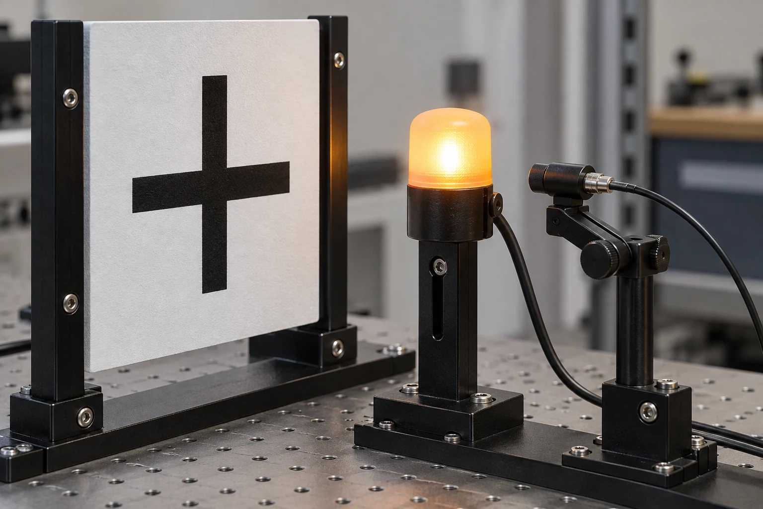
Establish the static reference. Aim at a fixed cross target, record its image position and angle, then repeat at several steady positions. This checks the axis direction and reference transformation without motion hiding a sign or zero error.
-
Check exposure timing independently. Place a pulsed light beside the target and record its electrical drive on a logger tied to the common timebase. A photodiode can record when light actually appears. Use a source both the camera and photodiode can detect, and account for detector and logger delay. Compare the optical pulse interval with the saved image’s exposure interval across repeated flashes. The frame’s integration interval limits how tightly a visible flash locates time; do not treat its first bright frame as an exact instant.
-
Test the complete angle pairing. Sweep past the target in both directions at recorded speeds. Compare the target’s image position against the time-aligned angle history. Use static alignment data and calibrated camera geometry to interpret the crossing. An error that reverses with direction and grows with speed suggests timing; a fixed offset suggests alignment. Mechanical hysteresis can also depend on direction, so the independent timing witness remains necessary.
-
Exercise the data boundary. Repeat with normal recording load, an agreed interruption of the angle feed, a zero crossing and a device restart. Record missing samples, clock discontinuities and any change of timestamp meaning. Clear incompatible history after a restart; preserve the session identity in exported records.
Accept the configured association only against the agreed error allocation. If clocks disagree, fix their mapping; if motion gaps are too large, shorten them or restrict capture to verified stationary periods. Where sample time cannot be established, report that limitation explicitly and qualify a stationary capture method instead.
Keep the timing witness independent of the software being commissioned.
Download the full article (PDF)
Related reading: A Precise Map Pin Can Share the Wrong Reference · Why a Repeatable Positioner Can Still Point Wrong