Unlimited Rotation, Finite Electrical Margin
A rotary joint can turn freely while its electrical path still limits the system. Follow the current out and back, see why digital signals need more than continuity, and translate movement into a useful maintenance record.
Download the article (PDF)PDF · 826 KB
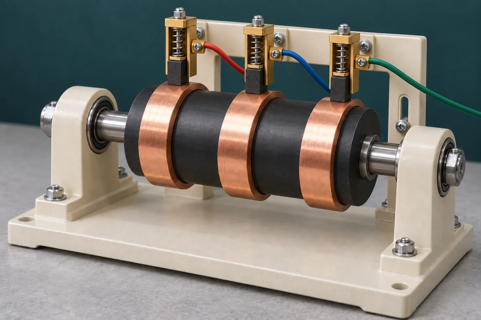
The axis can keep turning. Its connections still need a plan.
The appealing part of continuous rotation is easy to see: a camera can pass the same bearing again without winding up its service cable. The less visible part is a moving electrical boundary. Every connection that crosses it needs a defined job, current, return path and signal requirement.
A common slip-ring arrangement uses a stationary brush touching a conducting ring on a rotating hub. The brush stays in place while fresh ring surface passes beneath it. Separate rings carry separate electrical paths. The open teaching rig shows that contact principle; it does not depict the internal construction of an Inventra S³ product.
The PED10 specification lists continuous pan travel, 60 slip-ring lines, a 1 Gbit Ethernet signal, and a separate group of 52 lines rated at 2 A. These entries deserve to stay separate in an integration drawing. They do not establish that all 60 lines are interchangeable, that every line is free for a payload, or that spare lines may be joined to carry more current.
A useful allocation starts with complete circuits. A DC supply needs an outgoing conductor and a return. A differential signal uses a defined pair. Shield connections have their own purpose; they are not spare power returns by default. Reserve these functions before counting what remains.
Ask for the current connection drawing and identify the rotating and fixed endpoints of every path. That single exercise often exposes the real constraint: the desired camera upgrade may fit the cradle while needing an electrical interface that the selected configuration does not provide.
Available movement and available electrical paths are separate specifications.
The return path spends voltage too
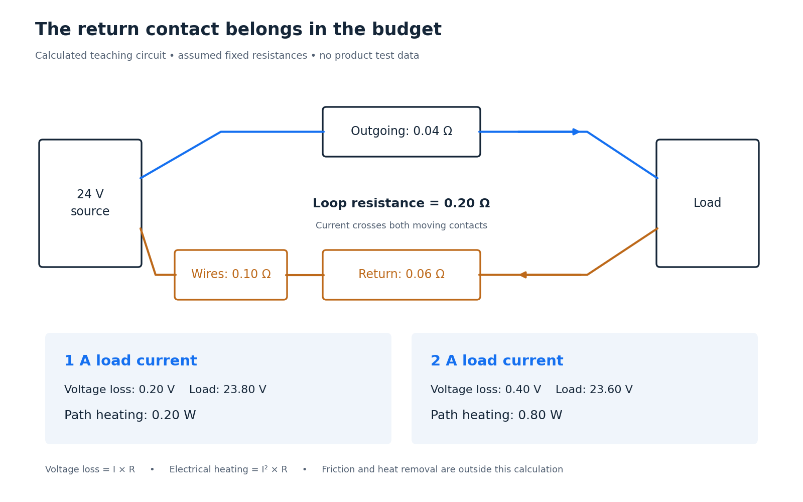
Consider a generic 24 V teaching circuit with assumed resistances: 0.04 Ω in its outgoing moving contact, 0.06 Ω in its return contact, and 0.10 Ω in the remaining wiring. These values describe an example, not PED10 measurements or design limits.
The load current passes through all three contributions. Total loop resistance is 0.20 Ω. At 1 A, the wiring and contacts lose 0.20 V, leaving 23.80 V across the load. At 2 A, they lose 0.40 V, leaving 23.60 V. The relevant voltage is measured between the load’s own supply and return terminals.
The heating changes faster. From P = I²R, total path heating rises from 0.20 W to 0.80 W when current doubles. Half of that example resistance is in the two contacts, so their combined electrical heating rises from 0.10 W to 0.40 W. This excludes mechanical friction and does not predict temperature; temperature also depends on how heat escapes. The equations follow the electrical power relation.
Now let one contact’s resistance briefly rise by an assumed 0.05 Ω during movement. At a constant 2 A, that adds 0.10 V of instantaneous drop. An average reading can conceal the brief event. Capture the load voltage with sufficient time resolution for the interruption the receiving equipment can tolerate.
Source supply-to-return voltage minus load supply-to-return voltage gives the complete path’s voltage loss. A four-terminal measurement separates an accessible, isolated contact path’s resistance from test-lead resistance. Confirm performance with the actual load and intended motion.
For fixed resistance, doubling current doubles voltage loss and quadruples electrical heating.
A continuity check cannot certify a data channel

A continuity meter answers a low-frequency question: is there a conducting path? A fast data connection asks another question: does the received waveform still preserve the information sent? Both tests can be useful, but they establish different things.
A transmission line has a characteristic impedance set by its geometry and materials. A mismatch reflects part of a travelling signal. For a simple lossless line, a 50 Ω line ending in 75 Ω has a voltage reflection coefficient of (75 − 50) / (75 + 50) = 0.20. The reflected voltage wave is one fifth of the incident wave under these transmission-line boundary conditions. This is a termination example, not a model of a particular slip ring.
The practical implication is that a channel must be specified as a channel, including its connectors, cables and rotary interface. Low DC resistance alone cannot establish bandwidth, impedance control or acceptable error performance. A nominal network speed also does not prove uninterrupted useful video through every operating condition.
Build a controlled comparison. First establish a stationary baseline with the actual endpoints, cable lengths, settings and traffic. Then rotate through the intended speeds and directions while recording link errors or interruptions and the load voltage on the same time basis. Repeat suspicious conditions. Where practical, a qualified temporary bypass can help separate an interface problem from an endpoint problem.
A cable wrap remains a reasonable alternative for limited travel. Its flexible loop avoids sliding electrical contacts, but its bend radius, repeated flexing and available movement still need qualification. Choose the architecture from the required path through space and the evidence for its connections.
Test the complete signal path under movement, with a stationary baseline for comparison.
Count movement without turning it into a life promise
A revolution rating becomes useful when paired with an operating record. For an assumed continuous speed of 6 revolutions per minute and 365 operating days per year, compare two schedules against an example 30-million-revolution allowance:
| Daily running time | Revolutions per day | Equivalent travel years |
|---|---|---|
| 8 hours | 2,880 | 28.5 |
| 24 hours | 8,640 | 9.5 |
Those are arithmetic conversions, not predicted service lives. Although PED10 publishes a 30-million-revolution rating, the applicable load, environment and maintenance conditions still matter. Ask for the conditions behind the rating before comparing it with an installation’s intended life.
For reversing motion, net angle is especially misleading. Moving 90° outward and 90° back produces zero net rotation but 180° of absolute travel. Keep absolute travel, reversal count and dwell time as separate records. Dividing absolute travel by 360° gives equivalent travel revolutions; it does not prove that a reversing duty causes the same wear as continuous rotation.
A brush experiment shows why one simple wear rule is unreliable. Turel, Slavič and Boltežar tested metal–graphite brushes against copper rings while allowing the brushes to move in their holders. They varied current, speed and temperature across 45 operating conditions. Electrical resistance and wear did not move together under every condition. In one group of tests, increasing ambient temperature reduced contact resistance while increasing wear.
Their measurement method adds another useful lesson. Attaching a displacement sensor could have changed the light brush’s motion, so they tracked its position with images and checked wear manually before and after testing. A test fixture can alter the behaviour it is meant to measure.
These results concern the study’s material pair, brush loading and laboratory conditions. They give no reason to increase an installed positioner’s speed, current or temperature. They do show why a qualification record should include both electrical function and wear evidence under the relevant duty.
A defensible maintenance plan therefore joins three records: what electrical path was qualified, how the unit actually moved, and what functional changes were observed. That turns an impressive travel number into evidence an owner can use.
Travel arithmetic describes usage; qualification and condition records establish what that usage means.
Download the full article (PDF)
Related reading: The Battery Reads 24 V. Why Does the Camera Still Restart? · Why a Repeatable Positioner Can Still Point Wrong