Integrating an EO/IR System on a Vehicle — Power, Bus and EMC
The three interfaces that decide whether an integration takes two weeks or two months, and what to settle before the hardware is ordered.
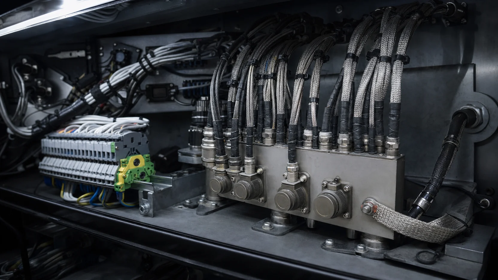
A gimbal that meets every optical requirement can still fail an integration. What fails is rarely the imaging. It is the power rail, the bus and the electromagnetic environment — three interfaces that are cheap to settle on paper and expensive to discover on a vehicle.
Power
Vehicle supplies are not benign. A 24 V nominal system sees load dump, cranking dips and reverse transients that a bench supply never produces. Units in this range accept an 18–32 V DC band, which covers a nominal 24 V vehicle with margin at both ends.
Two figures to establish early:
- Peak draw, not average. A positioner accelerating two axes against a hull that is pitching draws far more than its steady-state figure. Momentary peak torque ratings of 120 Nm and 225 Nm exist because that transient is real, and the current follows the torque.
- Cold-start behaviour. A heater option, or a cooled unit’s cool-down, puts its largest demand on the coldest morning — exactly when the battery is weakest.
There is a third figure that only appears on the vehicle: the voltage at the end of the cable. A harness sized for average current will hold nominal voltage all day and then sag on the first hard slew, because the drop is proportional to the peak, not the mean. A unit that browns out at the bottom of its input band during acceleration is usually diagnosed as a fault in the unit. It is a fault in the conductor cross-section. Size the harness against the peak-torque current, and measure the voltage at the connector rather than at the battery.
The bus
Control and video are separate decisions, and conflating them costs cable.
Control in this range runs over RS-422, RS-485 or Ethernet. Serial is robust, simple and easy to integrate into an existing crew station. Ethernet carries control and compressed video on one physical link, which is usually decisive on a small platform where every cable crossing the hull is a penetration to seal.
Video is HD-SDI, HDMI or Ethernet depending on the unit. H.264/H.265 compression over Ethernet is the low-cable option; HD-SDI is the low-latency option. If an operator is driving a positioner by hand while watching the image, latency is not a detail — it is the difference between usable and unusable. A compressed link that adds delay does not degrade the picture; it degrades the operator, who overshoots, corrects, and overshoots again.
Slip rings decide what can cross a continuously rotating axis at all. The 60-line and 24-line slip rings carry Ethernet and HD-SDI along with power. Count the lines you need before selecting the axis, not after.
Counting lines is necessary but not sufficient. A slip ring is a moving electrical joint, and a moving joint has a contact resistance that varies as it turns. Power and robust digital signalling tolerate that. Low-level analogue and marginal high-rate differential pairs are the ones that show it, and they show it as intermittent noise that correlates with azimuth — which is the hardest kind of fault to chase, because it disappears whenever the axis is parked for testing. Decide early which signals genuinely have to cross the axis, and convert the rest into something the joint tolerates before it gets there.
EMC
A vehicle is a dense electromagnetic environment: alternator, radios, ignition and now your imaging chain, all sharing a chassis ground. Systems in this range are designed to MIL-STD-461, and electrical connections follow MIL-DTL-38999.
Four practical points:
- Bonding. A carefully shielded harness terminated to a poor ground is an unshielded harness. Bonding straps and their impedance are part of the design, not a fitting detail.
- Chassis ground is not one potential. During a starter crank, hundreds of amperes return through the vehicle structure, and two boxes bonded at opposite ends of that structure will not agree on what zero volts is. The difference appears across the shield of whatever cable joins them, which is the origin of most of the hum bars and rolling artefacts that get blamed on the camera. Where two ends of a link have to sit at different potentials, the link has to be designed for it rather than grounded harder at both ends.
- Routing. Keep the video and control runs away from the alternator and radio feeders. Where they must cross, cross at right angles.
- Test the integrated vehicle, not the box. A unit that passes MIL-STD-461 standalone can still fail on a platform. The qualification of the component is a precondition for the integration test, not a substitute for it. The case that most often gets missed is the platform’s own transmitter: a radio keying a few metres away is a harsher radiated environment than a chamber reproduces, and it is the one source no external laboratory will test for you because it belongs to your vehicle.
Connectors mate or they do not
MIL-DTL-38999 is a good specification to see in a document, and it is not a guarantee that two parts will go together. The same shell size and the same insert arrangement are produced in several keying positions, precisely so that adjacent connectors on the same platform cannot be cross-mated by a tired crew at night. The consequence is that a correct-looking part number can still be the wrong part, and the discovery happens with the harness already on the vehicle. Agree shell size, insert arrangement, keying position and pin allocation as one item, in writing, and treat the pinout drawing as part of the order rather than as documentation that follows it.
What to settle before ordering
Supply voltage band and peak current, control bus and whether video shares it, connector type and full keying and pinout, slip ring line count and which signals cross the axis, mounting interface and bolt pattern, and the EMC test the whole platform must eventually pass. All of them are cheap to answer in an email and expensive to answer on a vehicle.