A Connected Thermal Camera Can Show You the Past
A green connection indicator can sit beside an old image. Learn how to separate video arrival, scene freshness, temperature settling and useful operation—and build a ready indication that notices when any of them stops working.
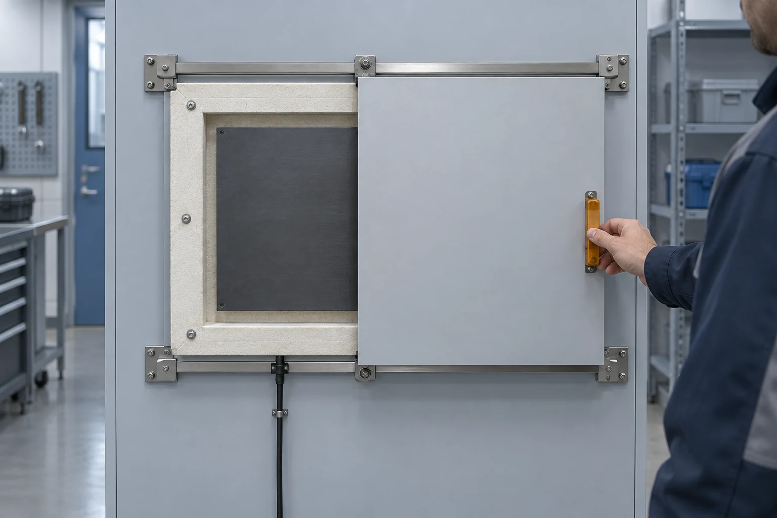
The clock can move while the picture stands still
Imagine an operator watching a closed maintenance door. The connection indicator is green and the screen clock keeps counting. Outside, someone opens the door. On screen, it stays closed. The application can still be running while it displays the last available camera frame.
A rising packet count is incomplete evidence too. In the Real-time Transport Protocol (RTP), several packets can belong to one frame and share its timestamp. Packet sequence numbers describe packet delivery; they are not a count of newly exposed images. A zero-loss report can also hide delay: the cumulative-loss calculation still treats late packets as received. See RFC 3550, sections 1, 5.1 and 6.4.1.
Even normally flowing video has age. Capture, encoding, buffering, decoding and presentation occur at different points. A buffer can smooth uneven arrivals while making the displayed scene older. The GStreamer latency documentation shows why a live source and a display do not automatically share zero delay.
Give the image something it must follow
Move an opaque mask across a warm, stable surface. Its exposed shape changes clearly in the thermal view, without needing a precise temperature reading. Watch that change on the final operator display. Repeat the movement at irregular intervals so a repeated short recording cannot look convincing merely because its rhythm matches the test.
For an end-to-end timing check, use one reference recording that includes both the physical mask movement and the display. They then share a recording clock. The reference camera’s frame interval and exposure limit the timing precision, so retain those settings with the result. This test answers a concrete question: how long after the scene changes does the operator see it?
Prove that the displayed scene follows a real change; a moving indicator is not enough.
Three different processes can delay a useful view
“Warming up” often hides several different mechanisms. Their effects—and the evidence that they have finished—are different.
| Process | What changes? | What to observe |
|---|---|---|
| Detector cool-down | A cooled detector approaches its specified operating temperature | Model-specific detector status and valid imagery |
| Temperature settling | Electronics, optics and housing redistribute heat | Image behaviour under the required starting conditions |
| Nonuniformity correction | Pixel responses are adjusted against reference information | Correction status, interruptions and subsequent image quality |
Cooling can suppress internally generated detector current. Reaching the required temperature is one physical milestone, followed by checks that the instrument behaves correctly. NASA’s account of its infrared instrument commissioning makes that distinction clear. Read the cooling and checkout sequence. Its timings and temperatures belong to that spacecraft instrument.
An uncooled camera has no cryogenic cool-down stage, but its own heat can still change its response. In a University of California, Merced study, researchers alternated still air and fan airflow while viewing a uniform foam surface. The recorded image temperature showed sawtooth-like jumps associated with correction events during warmup. That experiment concerned temperature data; it did not establish a universal waiting time before an operator can see useful detail. See section 3.2 of the study.
Some cameras make a nonuniformity correction by briefly closing a shutter over the detector. During that interval the detector cannot see the external scene. NIST describes the mechanism. Whether the output pauses, holds a frame or signals invalid data depends on the implementation.
A crisp image may therefore arrive before stable temperature measurements are possible. Define those two uses separately, and request calibrated radiometry only when the task needs temperatures.
A correction event, a settled camera temperature and a useful image are separate observations.
Ready can become false
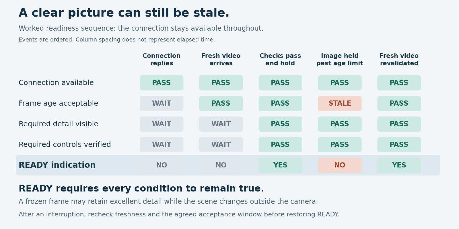
For an equipment-viewing task, define ready as four conditions being true together: communication works; displayed frames are recent enough; the required detail is visible; and the operator’s required controls have passed a response check. Require these conditions to persist for an agreed observation window rather than accepting one good frame.
The matrix shows a worked sequence. A connection replies first, then fresh video arrives. Detail and control checks follow. Later, the display holds an old frame beyond the allowed age. The picture remains sharp and communication still works, but ready must clear. Recovery requires fresh video and the acceptance checks again.
Decide what “recent enough” means
Frame age is display time minus the exposure timestamp, with both expressed on a common timebase. An arrival timestamp measures a different event. Relabelling a delayed frame when it arrives makes the delay disappear from the number, not from the picture.
For RTP, relate the media timestamp to a reference clock before comparing it with display time. RTP timestamps have their own rate and initial offset; they are not directly readable wall-clock times. RFC 3550 explains the clock mapping.
Suppose a trial sets a 200 ms maximum frame age. An estimated age of 180 ms with a bounded timing error of ±40 ms could mean a 220 ms old image. That does not establish compliance with the limit. Improve the timing measurement or include the error bound in the acceptance rule. These numbers define a test example, not a camera specification.
If exposure timing is unavailable, use the physical scene-change test to assess end-to-end delay. State what it measures. A scene-change test cannot reveal every internal delay separately, but it can expose a misleadingly healthy-looking display.
Remove the ready indication when freshness fails, even if the connection and visible detail remain intact.
A quick restart does not reproduce an overnight start
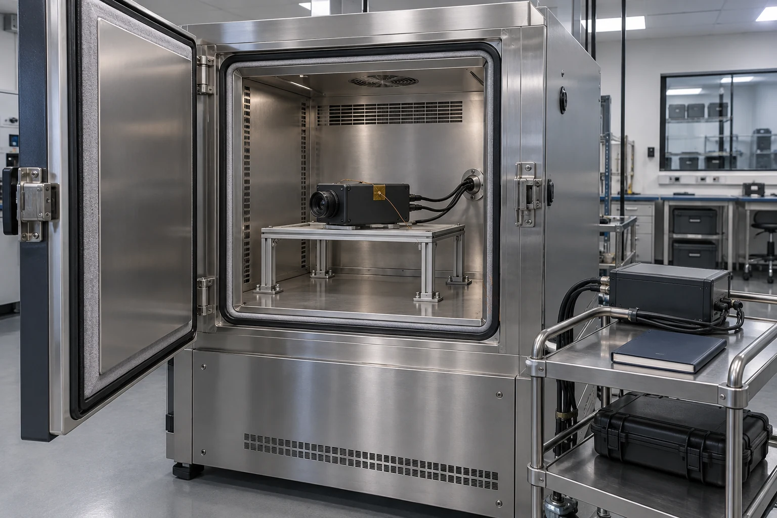
A short power interruption leaves heat stored in the camera. An overnight shutdown lets the assembly move toward its surroundings. Those are different starting states, even when the same power switch starts the stopwatch. A chamber or controlled room helps repeat the starting condition; an external probe records housing temperature but does not replace detector status.
Record the initial environment, measured housing temperature, power-off duration, power supply, camera configuration and software version. Begin timing at an observable event, such as valid power at the equipment input. Finish at the operator display after the required observation window. Saving only a camera-side first-frame time leaves the downstream video path untested.
Include three deliberate observations in the run:
- Move the mask after the first picture appears. Confirm freshness before accepting the image.
- Observe a normal correction event where the selected camera supports one. Check how its interruption is reported and how the ready state recovers.
- Use the test setup to hold or interrupt video while keeping the control connection available. Confirm that a stale image clears ready, then verify recovery when fresh frames return.
Keep a time-stamped event log beside the recording: first response, first verified fresh image, first useful view, control response, interruptions and restored readiness. Repeat under the expected starting temperatures and power-off conditions. Report the spread of results, not just the fastest run.
For an Inventra S³ thermal-imaging configuration, ask which detector, correction and image-validity status signals are available through the chosen interface. Agree how the host interprets them. The useful outcome is a ready indication the operator can trust because it represents the current view and required functions, and withdraws when that evidence is lost.
Start from known conditions and finish at the actual display; keep recovery behaviour in the same test.
Download the full article (PDF)
Related reading: Why the Strongest Infrared Band May Not Give the Clearest Image · The Newest Angle Can Belong to the Wrong Image
Sources and further reading
- RTP: A Transport Protocol for Real-Time Applications — RFC 3550
- GStreamer Design: Latency
- Webb Telescope’s Coldest Instrument Reaches Operating Temperature
- A Detailed Study on Accuracy of Uncooled Thermal Cameras by Exploring the Data Collection Workflow
- Evaluation of Image Quality of Thermal Imagers Used by the Fire Service
- Inventra S³ Thermal Imagers