Height buys range; deflection gives it back
A 15 m mast widens the horizon — but a few centimetres of deflection at the top become tens of metres of miss distance at 5 km. That conversion is what the design is really about.
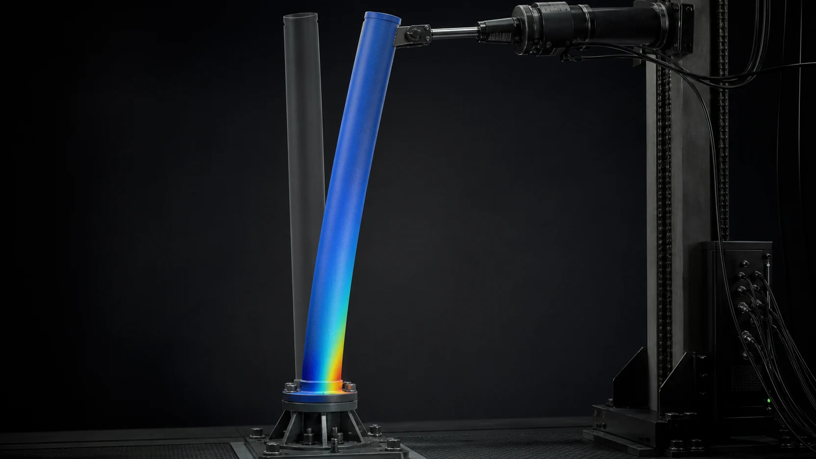
Why go up
Raising a sensor from 3 m to 15 m buys two concrete things: the geometric horizon extends (from roughly 6.2 km to 13.8 km over flat ground), and the dead zones created by nearby obstacles — brush, walls, vehicles — close up. For fixed-site surveillance that is coverage gained without installing another sensor.
The price is mechanical: every metre of height increases both the wind moment arm and structural compliance.
Wind load in order-of-magnitude terms
Dynamic pressure scales with the square of velocity:
q = ½ · ρ · v² · (ρ ≈ 1.225 kg/m³)
At 25 m/s (about 90 km/h), q ≈ 383 Pa. Take a payload with 0.5 m² of frontal area and a drag coefficient C_d ≈ 1.2, and the force on the payload alone is ≈ 230 N. Over a 15 m arm that is an overturning moment of 3.4 kNm at the base — before adding the drag of the mast body itself.
The real message is not the magnitude but the square-law scaling: double the wind speed and the load quadruples. This is why “what wind will it operate in” and “what wind will it survive undamaged” are two separate specifications and must never be merged.
From deflection to pointing error
Horizontal tip deflection δ converts directly into angular error: θ ≈ arctan(δ / h). For a 15 m mast:
| δ (tip deflection) | θ | Miss at 5 km |
|---|---|---|
| 50 mm | 0.19° | ~17 m |
| 100 mm | 0.38° | ~33 m |
| 200 mm | 0.76° | ~67 m |
| 400 mm | 1.53° | ~133 m |
This table turns “how rigid is the mast” into “how accurate is the system”. If your pan-tilt positioner offers 0.04° pointing accuracy, a 0.38° structural deflection renders that figure meaningless — the positioner’s budget disappears next to the mast’s.
The critical distinction: static deflection can be compensated, dynamic deflection cannot. The mean bend produced by a steady wind can be taken out by calibration or a pre-engagement correction. Gust-driven oscillation is a real-time disturbance and can only be suppressed structurally or by gimbal stabilisation.
That compensation has a condition attached to it, and it is easy to promise and hard to keep: to correct for a steady wind you have to know the steady wind, at the top of the mast, now. An anemometer at the base of the structure is measuring a different flow from the one bending it. A correction driven by the wrong wind speed is not a smaller error than no correction; it is an error in a direction the operator is not expecting.
The bend that has nothing to do with wind
Point a mast at a fixed reference on a still, clear day and come back six hours later. It will not be pointing at the same place.
The face of the mast in the sun runs warmer than the face in shade. The warm side expands more than the cold side, and a column with a temperature difference across it bows away from the heat — the same effect that curves a bimetallic strip, acting on a structure ten or fifteen metres long. The bow is small in absolute terms and it is an angle, which is the unit this whole article is about. Because the sun moves, the direction of the bow rotates through the day, so the error is not a fixed offset that a one-time boresight removes. It is a slow diurnal wander.
Three consequences are worth carrying:
- A boresight alignment performed at nine in the morning is not the alignment the system has at three in the afternoon.
- Wind models do not predict this error, because the day it is largest is the calmest, clearest day — strong wind mixes the air and evens the two faces out.
- The mitigations are architectural rather than clever: a reflective or light-coloured finish, a section that conducts heat around itself rather than holding a gradient, or a reference the system can re-boresight against periodically.
Natural frequency: the specification everyone forgets
A mast is a long, relatively compliant cantilever; its first bending mode typically sits between 1 and 4 Hz. Two risks follow:
- Wind turbulence carries much of its energy in the 0.1–2 Hz band. If the natural frequency falls inside that band, even a modest wind produces sustained oscillation.
- Vortex shedding excites in a narrow band: f ≈ St · v / D. With a Strouhal number St ≈ 0.2 and a body diameter D = 0.15 m, a light 2 m/s breeze produces excitation at ≈ 2.7 Hz — an unfortunate coincidence with the natural frequency of a typical mast, and one that appears on a calm day rather than in a storm.
Hence our practical design target: keep the first mode in the extended position above 3 Hz, and ensure it does not coincide with the shedding frequency across the design wind range.
Why that coincidence is worse than a coincidence
Read the shedding formula literally and the problem looks narrow: the wind has to sit at one particular speed for the excitation to line up with the structure, and wind does not do that for long.
Real structures do not cooperate. As the shedding frequency approaches the natural frequency, the shedding starts to follow the structure instead of the flow — the mast’s own motion organises the wake, and the shedding stays locked to the mast over a band of wind speeds rather than crossing through it. The effect is called lock-in, and its practical meaning is that the resonant condition is not a knife edge you pass through in a gust. It is a window the wind can sit inside for an afternoon.
A related failure mode is worth naming because it is often misread as shedding. Galloping is an instability of non-circular sections: it produces large-amplitude, low-frequency motion that grows with wind speed rather than locking to a frequency. A mast that is circular on the drawing may not be circular in service, because a cable ladder, an antenna bracket or an accumulation of ice has changed the cross-section into something the wind can push on asymmetrically. The clean structure that was analysed is not always the structure that is standing on the site.
Design trade-offs
| Option | Gain | Cost |
|---|---|---|
| Free-standing (unguyed) mast | Fast deployment, small footprint | Larger section, heavier base |
| Guyed mast | Far higher stiffness, lighter body | Setup time, land area, manpower |
| Pneumatic mast | Light, fast, quiet | Seal maintenance, locking required |
| Electromechanical mast | Intermediate stops, repeatability, remote control | Heavier, power draw |
| Mechanical locking stages | Markedly reduces deflection and creep | Extra mechanism, extra mass |
The point most often missed on pneumatic masts: pressure is there to lift. In the extended position the load should be carried by a mechanical lock, not by pressure. Otherwise internal pressure varying with temperature turns into slow creep at the top and a pointing error that grows through the day.
Conclusion
The right question when selecting a mast system is not “how many metres and how many kilograms” but: at the design wind speed, how many milliradians of error remain at the top, and how much of that is static versus oscillatory? The answer sets your sensor’s effective range. And ask the same question again with no wind at all, in the middle of a sunny afternoon, because that case has a different answer and a different cause.