The Requirement
See outside. Stay inside.
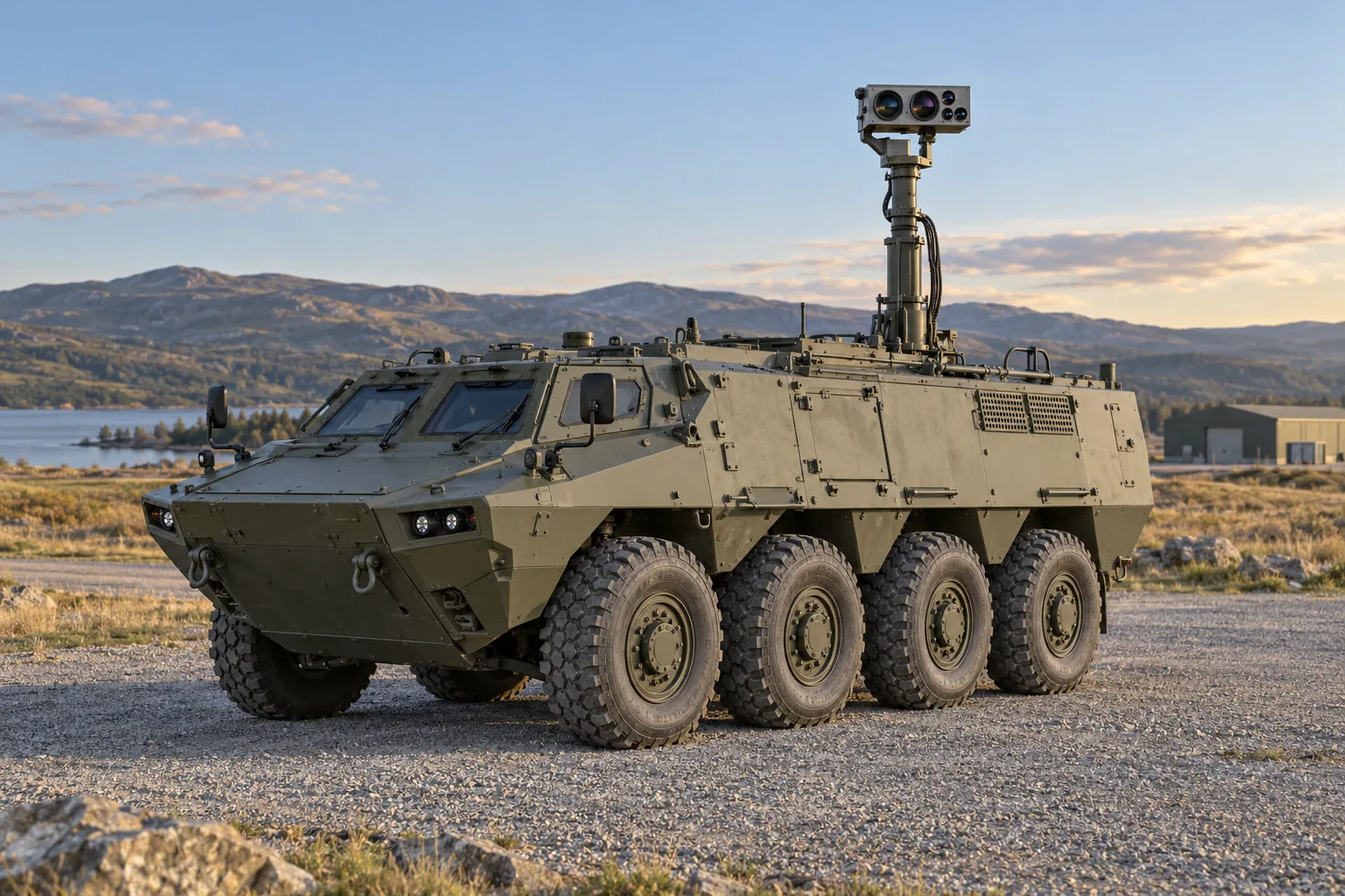
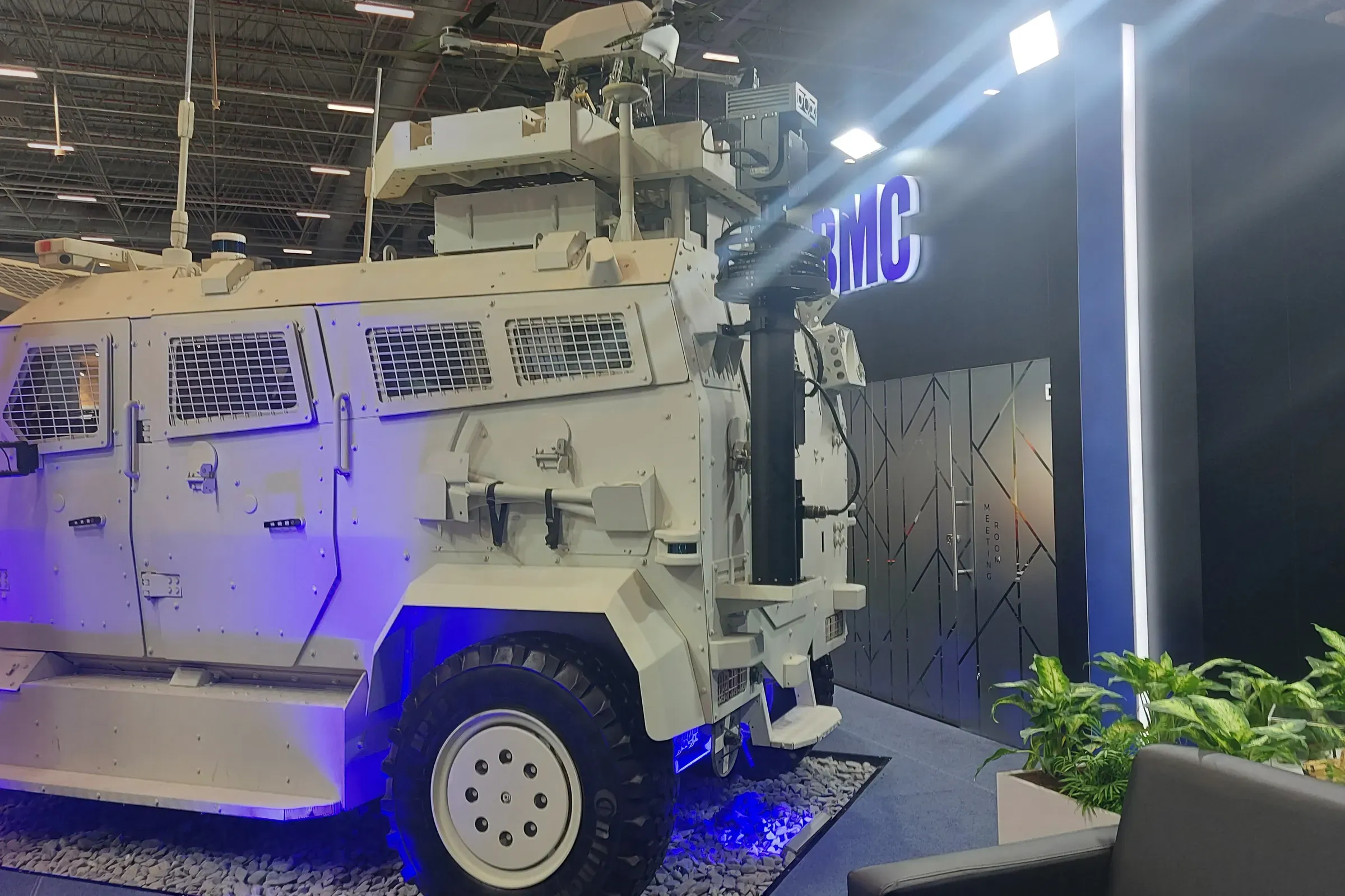
Need to see around your vehicle without leaving it? Inventra S³ supplies the mast and camera for this task. When parked, raise the camera above the roof and watch day or thermal images from inside. We help match the equipment to your vehicle.
Find your application
From light 4x4s to larger platforms.
Light protected 4x4s
Add a raised camera view to a smaller vehicle. We help fit the mast and camera to the available space.
Larger armoured vehicles
Bring an elevated day and thermal view to the crew of a larger wheeled platform.
Understand the application
A higher view, on the crew’s screen.
Look above the roof
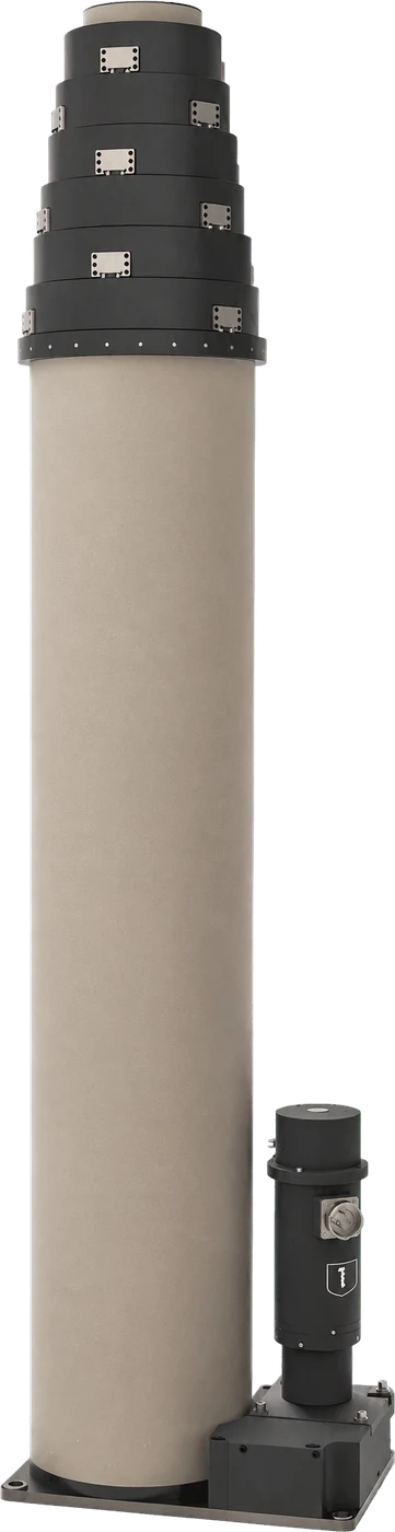
MES10 raises the camera for a higher viewpoint while the vehicle is parked.
See in two ways
The day camera shows visible detail. Thermal imaging shows differences in heat.
Stay at the screen
The crew watches and adjusts the camera view from inside the vehicle.
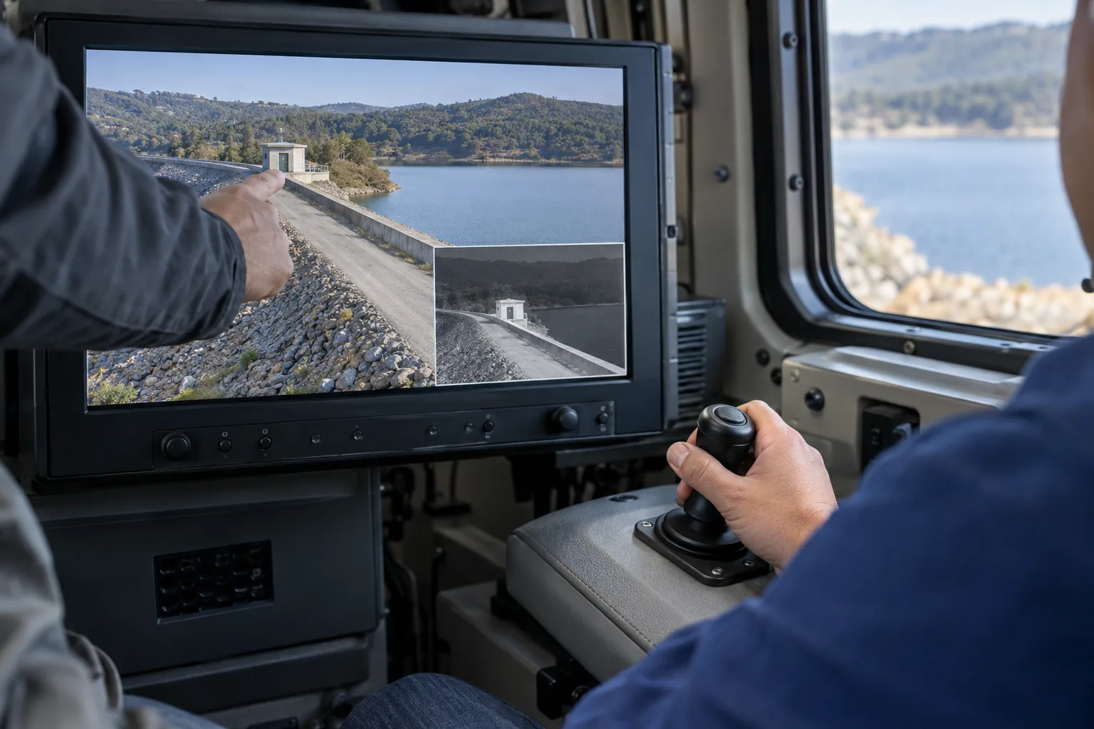
Camera above the roof. Viewing and control inside the vehicle.
How your team uses it
Watch and control from inside.
The operator uses a screen and controls inside the vehicle. The mast lifts the camera; the camera sends its view to the crew.
Raise the camera
With the vehicle parked, use the mast controls to lift the camera above the roof.
Choose the view
Watch day or thermal views on the crew’s screen.
Look closer
Use the connected camera controls to change direction and zoom.
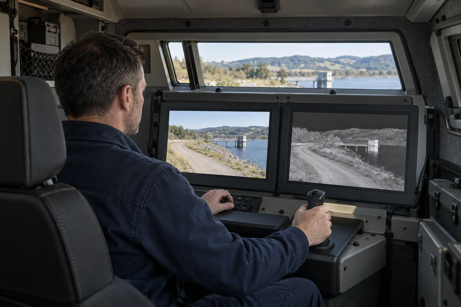
We select the camera steering, mounting and crew controls for your vehicle.
Recommended products
One mast. One camera. Different jobs.
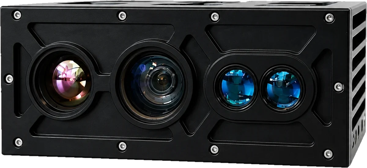
SEB20
Day and thermal camera
Shows visible scene detail and differences in heat, with zoom to look closer.
Explore SEB20
We select the camera steering, mounting and crew controls for your vehicle.
Every product qualified for this application
All Products| Model | Product | Family |
|---|---|---|
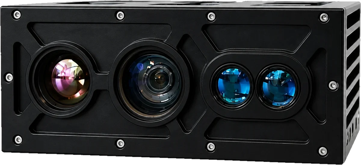 SEB20 SEB20 | Multi Channel (EO-MWIR-LRF-LD) Thermal Imager | Thermal Imagers |
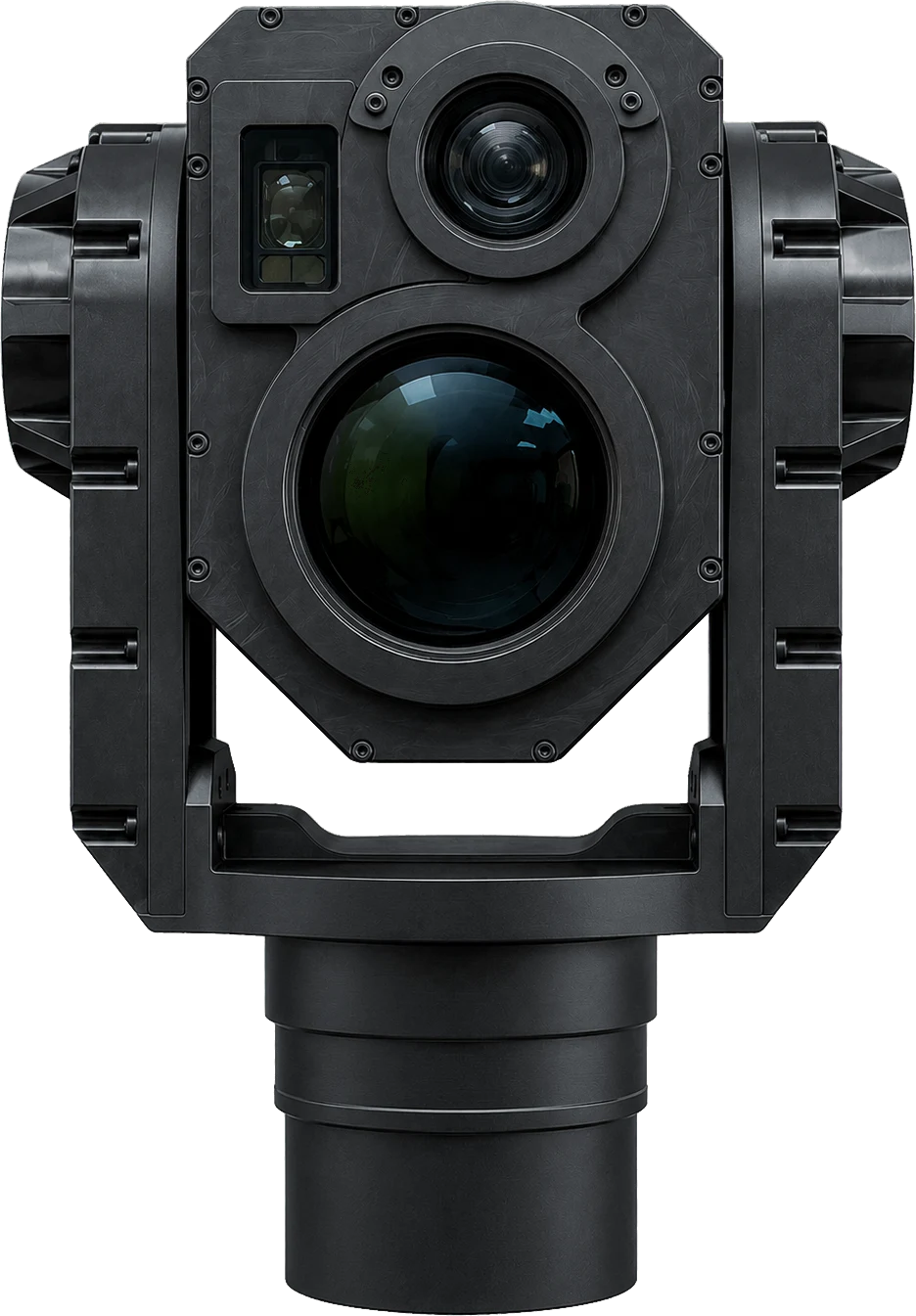 SEG14 SEG14 | Multi Channel (EO-LWIR-LRF) Stabilised Gimbal System | Thermal Imagers |
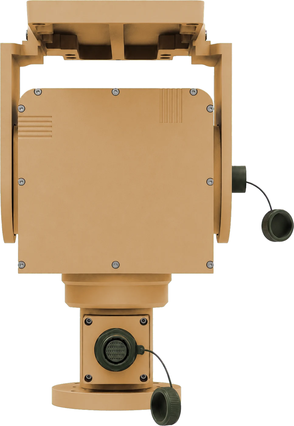 PED10 PED10 | Ultra Precision Electromechanical Pan-Tilt | Pan-Tilt & Positioning Systems |
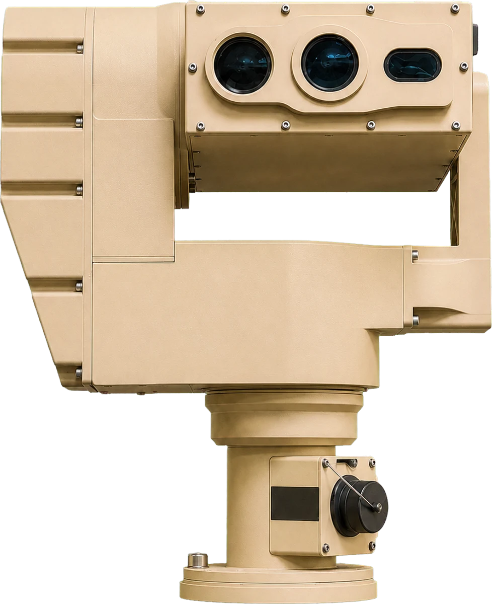 PED12 PED12 | Stabilised Electromechanical Pan-Tilt | Pan-Tilt & Positioning Systems |
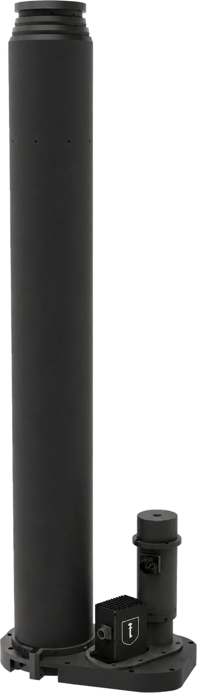 MEM10 MEM10 | Ultra Stable Electromechanical Mast System | Mast Systems |
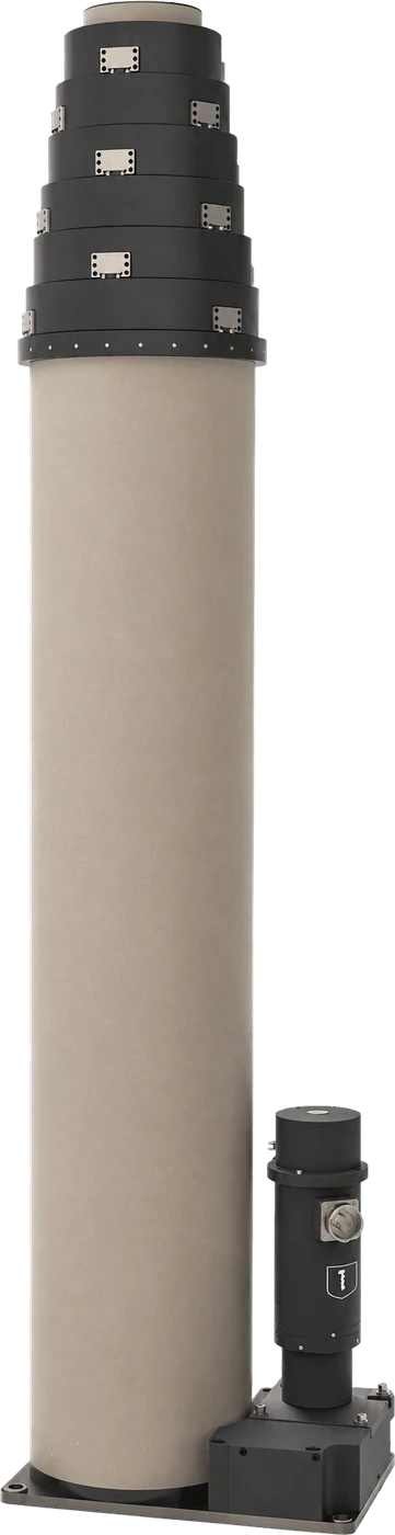 MES10 MES10 | Locked Electromechanical Mast System | Mast Systems |
Start with your requirement
Tell us about your vehicle.
Three simple questions
- Which vehicle do you use?
- What does the crew need to see?
- What space is available for the equipment?
A vehicle photo and a short description of what the crew needs to see are enough to start. We will help choose the setup.