A Heavy Tripod Can Still Move
Payload mass does not reveal how a tripod shares load with the ground. Trace settlement, changing foot reactions and cable pull, then record a repeatable mechanical check that separates a sound installation from a momentarily steady one.
- Extended Height
- 995 mm
- Rated Payload
- 150 kg
- Weight
- 14,7 kg
- Retracted Height
- 725 mm
The ground is part of the support
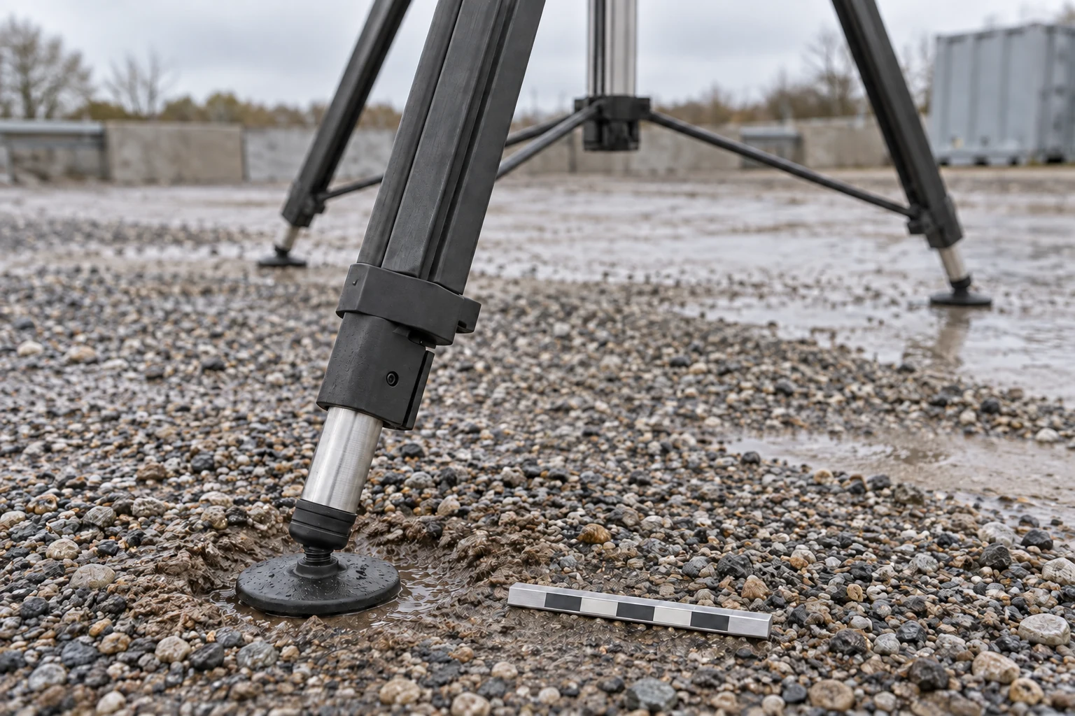
A heavy tripod can remain upright while its head slowly tilts. One foot compresses a soft surface, a cable tightens as the camera turns, or an offset payload changes the load shared by the legs. The useful question is whether the complete installation holds its required position throughout the intended operating conditions.
A payload rating applies to a defined support configuration. The Inventra S³ TMH10 product page lists different configurations and foot options, with installation and interface documents available. Those details belong in the setup record; a mass figure alone cannot establish the behaviour of the ground beneath it.
Foundation engineering distinguishes resistance to ground failure from limits on settlement. A surface can support a load yet compress too much for the attached instrument. Settlement also depends on soil history and time, so a short quiet interval cannot establish long-term behaviour. FHWA, Sections 8.3 and 8.5
Even apparently hard ground deserves attention. NOAA’s geodetic-leveling manual identifies tripod settlement on bituminous pavement and frozen ground, and warns that ground cover can cause settlement or rebound. These observations justify checking the surface rather than judging it by appearance. NOAA, Chapter 3
Consider a rigid support plane: foot A drops 1 mm while feet B and C remain fixed. The perpendicular distance from A to line B–C is 0.90 m. Its tilt is arctan(0.001/0.90), about 1.11 milliradians or 0.064°. This calculation isolates differential settlement; real leg and mounting flexibility can add motion. All three feet could instead sink equally with much less tilt.
A support can carry its load and still move enough to disturb the camera.
Follow the reactions, not just the mass
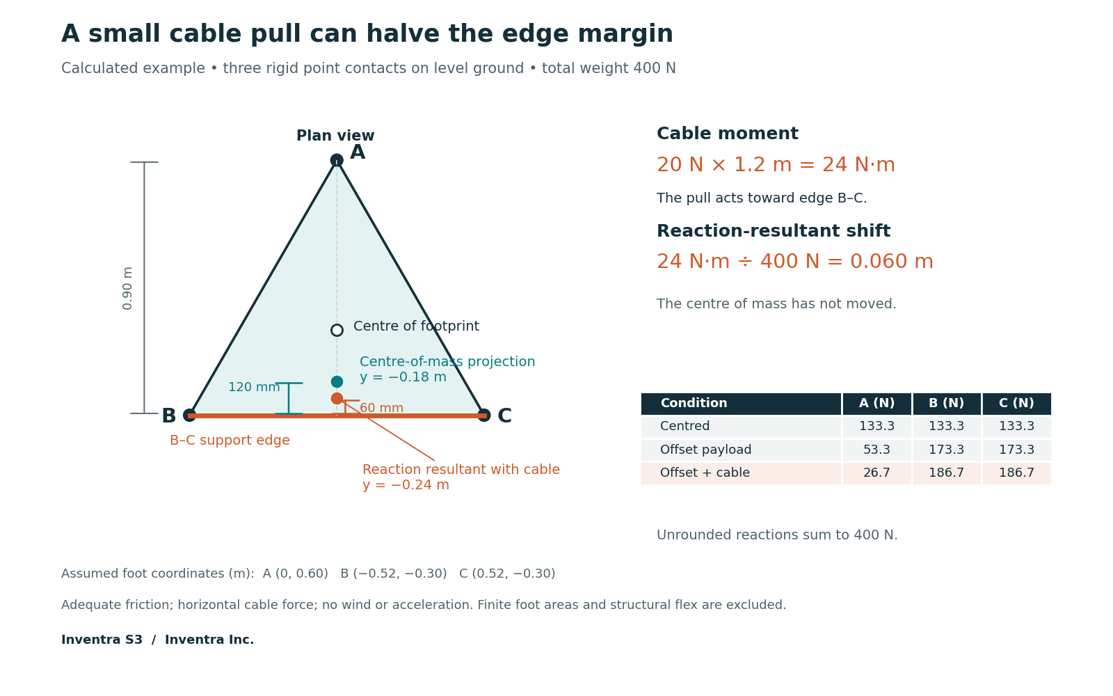
A ground reaction is the force a foot receives from the ground. For three ideal point contacts on level ground, join the contacts to form the support polygon. Under gravity alone, the centre-of-mass projection must lie inside that triangle for all three vertical reactions to remain positive. At an edge, the opposite foot unloads. This is an equilibrium condition, not proof against slipping, flexing or disturbance. Bretl and Lall, Sections I–II
For the calculated example, assume total weight W = 400 N, including tripod and payload. Foot coordinates, in metres, are A (0, 0.60), B (−0.52, −0.30) and C (0.52, −0.30). The combined centre of mass projects to (0, −0.18), only 0.12 m from edge B–C.
Force balance gives A + B + C = 400 N. Taking moments about B–C gives A × 0.90 = 400 × 0.12, so A carries 53.3 N and B and C each carry 173.3 N. Dividing total weight by three would miss this imbalance.
Now assume a horizontal cable pulls toward B–C with 20 N at a height of 1.2 m. Its 24 N·m moment shifts the combined vertical ground reaction by Fh/W = 0.060 m toward that edge. The centre of mass stays put, but the remaining edge margin halves. A falls to 26.7 N; B and C rise to 186.7 N each.
The model assumes sufficient friction, rigid contacts and no wind or acceleration. It supplies neither an allowable pull nor a tipping test. With finite feet, sloping contact surfaces or anchors, the actual contact geometry and force constraints require separate evaluation.
A cable can move the vertical reaction resultant while the centre of mass stays still.
Make cable influence observable
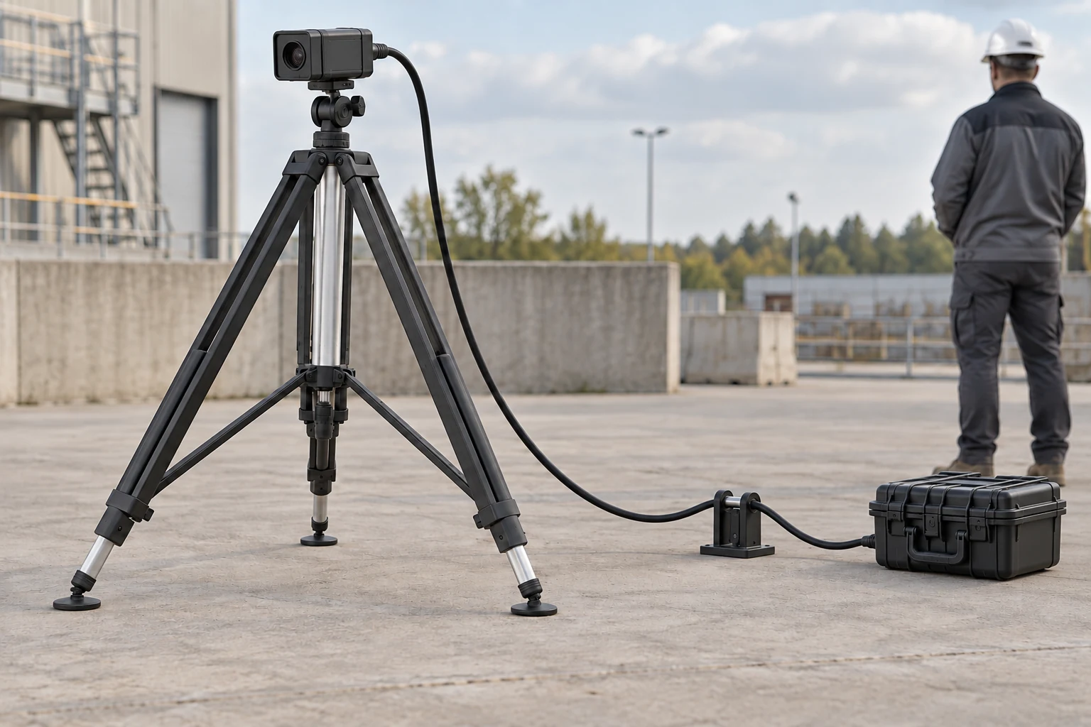
Strain relief protects a connector by carrying cable load elsewhere. If that restraint attaches high on the tripod, the force still enters the support. Moving an approved restraint lower reduces its moment arm; independently supporting the incoming run can reduce the load transmitted to the tripod. Neither arrangement guarantees a force-free moving loop.
Provide the cable’s specified bend radius and enough free length for the intended movement. NASA’s harness standard treats bend radius, connector stress relief and routing without continuous tension as separate design concerns. Use the actual cable and equipment instructions to choose dimensions and restraints. NASA-STD-8739.4A, Sections 7.2 and 8.1
Perform a comparison within the approved operating envelope. Keep the feet, payload, height and movement programme unchanged. In condition A, use the proposed field route. In condition B, support the incoming run independently while retaining a free moving loop. Keep connectors mated and record both arrangements. Observe clearance at the movement endpoints and during reversals, where a loop can catch or change shape.
Record head-base tilt with an independently checked two-axis inclinometer, alongside commanded position, time and the cable condition. An inclinometer does not measure yaw; add an independent azimuth reference where that motion matters. Return to the same parked position and dwell after each movement. A repeatable base-angle change at the same cable configuration makes cable loading a candidate; a residual shift may indicate slip, joint movement or settlement.
Use A–B–A, then reverse the order if practical. Otherwise, ongoing ground settlement could make the later condition look worse regardless of routing. Retain weather and foot measurements alongside the tilt trace. Do not pull a connector or approach foot lift-off to make the effect visible.
A connector can be protected while its cable still loads the tripod.
Keep a record that can fail usefully
Agree the permitted head-angle change, residual movement after a commanded cycle, observation duration and operating conditions before testing. Choose instruments whose uncertainty can resolve those limits. No universal settling time or angular threshold follows from tripod mass.
Identify feet A, B and C. Record their contact positions, foot types, leg extensions, ground condition and payload arrangement. Photograph each contact and the complete cable route. Use repeatable marks on the foot bodies, with additional marks above leg locks to distinguish extension slip. Use an external level reference on demonstrably stable ground; do not use a nearby soft patch as the reference for settlement.
For an initial record, readings at 0, 1, 5 and 15 minutes can reveal a trend. This is a proposed sampling sequence, not a qualification duration. Extend observation to the intended duty and expected ground or weather changes. Record the measurement time after payload installation and after each intervention.
| At each timestamp | Primary record | Additional detail |
|---|---|---|
| Foot positions | A, B and C elevations relative to the external reference | Visible sinking, sliding or loss of contact |
| Head base | Both tilt axes | Instrument resolution and uncertainty |
| State | Payload pose, parked or moving, route A or B | Time since movement |
| Site conditions | Rain, surface moisture, temperature and wind | Nearby traffic or footsteps |
A continuing foot-elevation trend calls for ground or foot-support changes and a fresh record. Stable feet with changing head tilt directs attention toward leg locks, mounting joints and cable forces. A change that follows cable condition in repeated comparisons calls for routing correction. Recheck the final route after any correction.
Adding mass may improve one overturning calculation while increasing ground pressure. Finish acceptance against the agreed mechanical limits for the installed configuration. Viewpoint reproduction and obstruction checks belong in the separate temporary-site tripod case.
Acceptance belongs to the recorded configuration and observation interval.
Download the full article (PDF)
Related reading: Same Weight, Three Times the Wind Load · A Small Tripod Move Can Hide the Inspection Panel