Accessories & Integration Components
ACP20
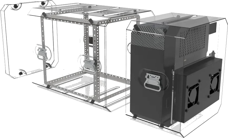
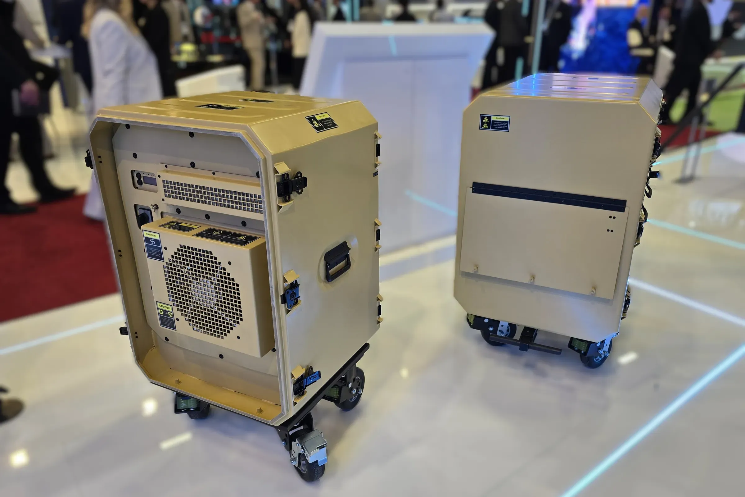
Portable Climatic Rack Cabin
Transportable 10U climate-controlled rack cabin with vapour compression cooling, silicone mat heating and optional EMI shielding, for field electronics.
- 10U
- 1.500 W
- 610 mm depth
- 1.500 W
- Cooling Capacity
- 10U
- Cabin Height
- 220 VAC
- Mains Voltage
Highlights
01Climate control
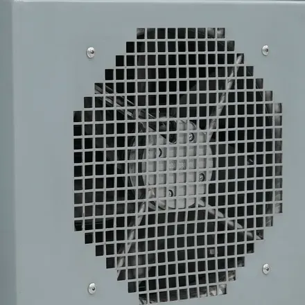
1500 W of vapour compression cooling
A vapour compression cycle with a compressor provides up to 1500 W of cooling, which is a different class from the fan and filter arrangement a passive cabin relies on.
- Heating through 750 or 1500 W silicone mats
- 10U chassis space, 610 mm depth
02EMI/EMC
Faraday cage with conductive sealing
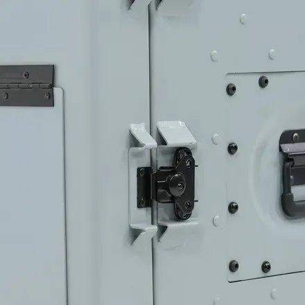
Shielding is available through conductive gaskets, wire mesh braid, embedded wire and Faraday cage construction, so the cabin can hold sensitive electronics next to a transmitter.
- Butterfly latch closure, aluminium 5xxx and 6xxx body
- Stainless steel fasteners throughout
Gallery
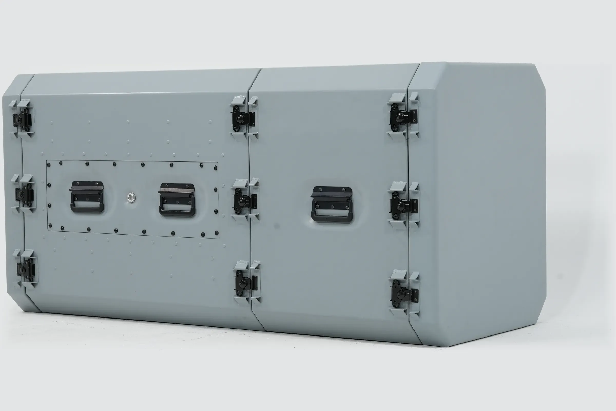
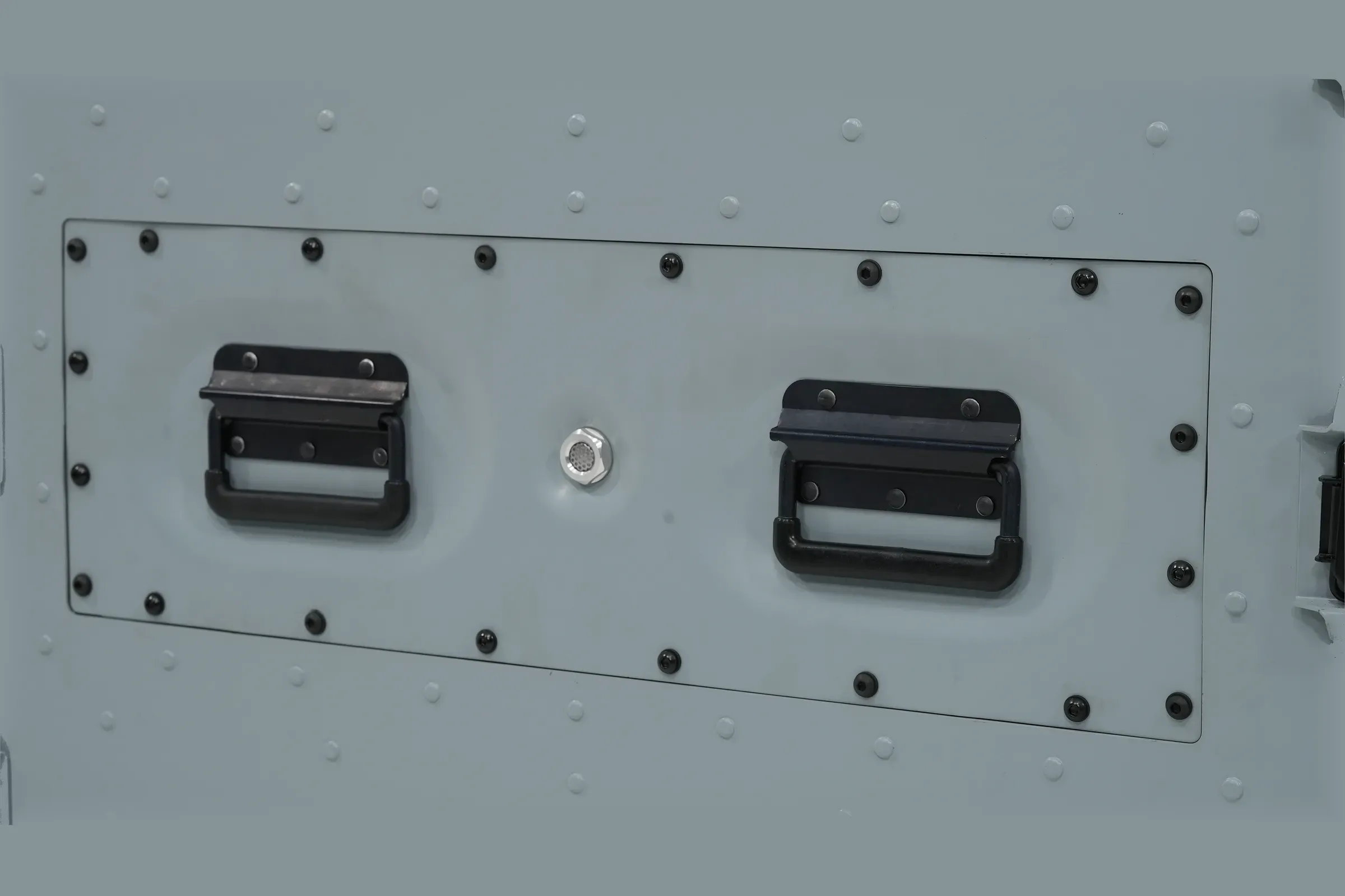
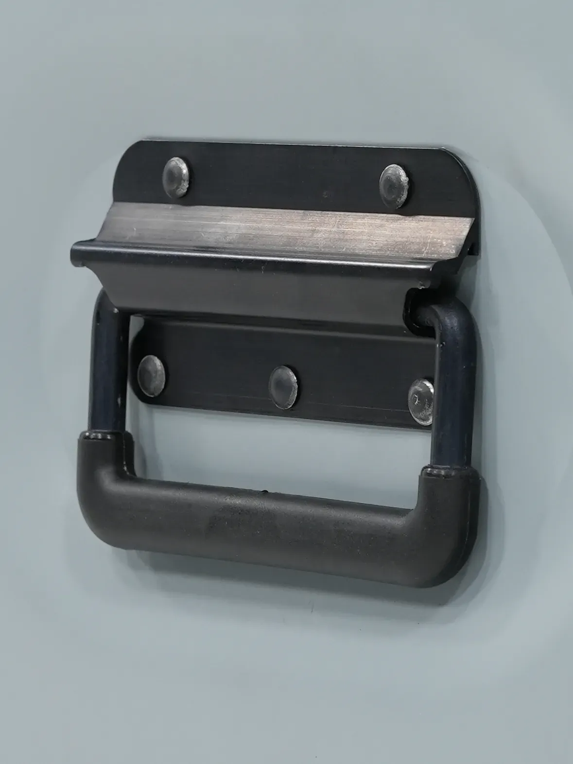
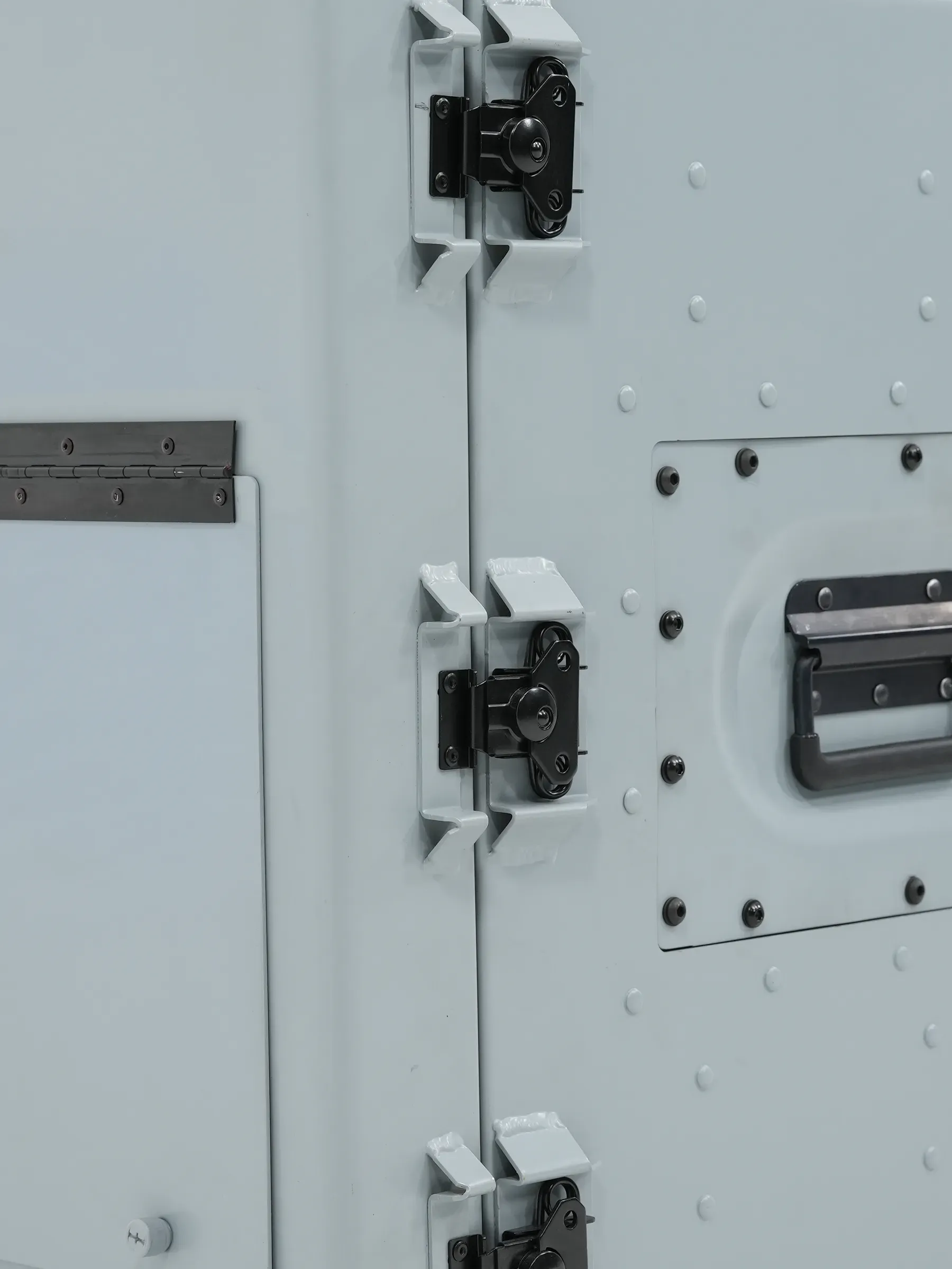
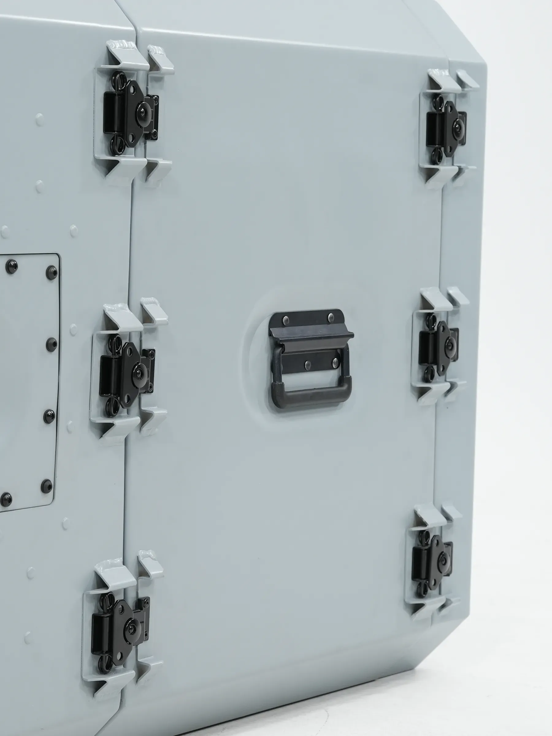
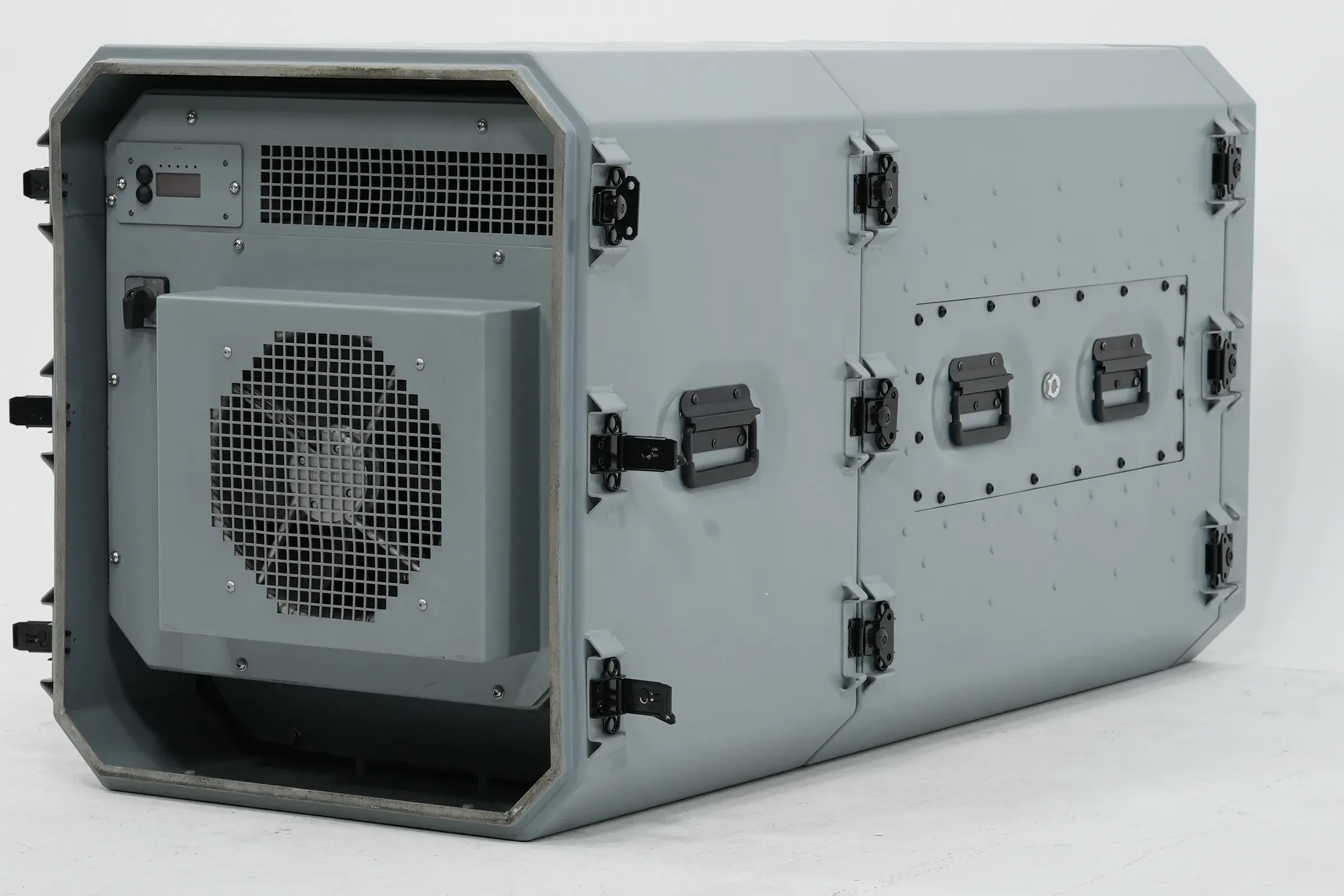
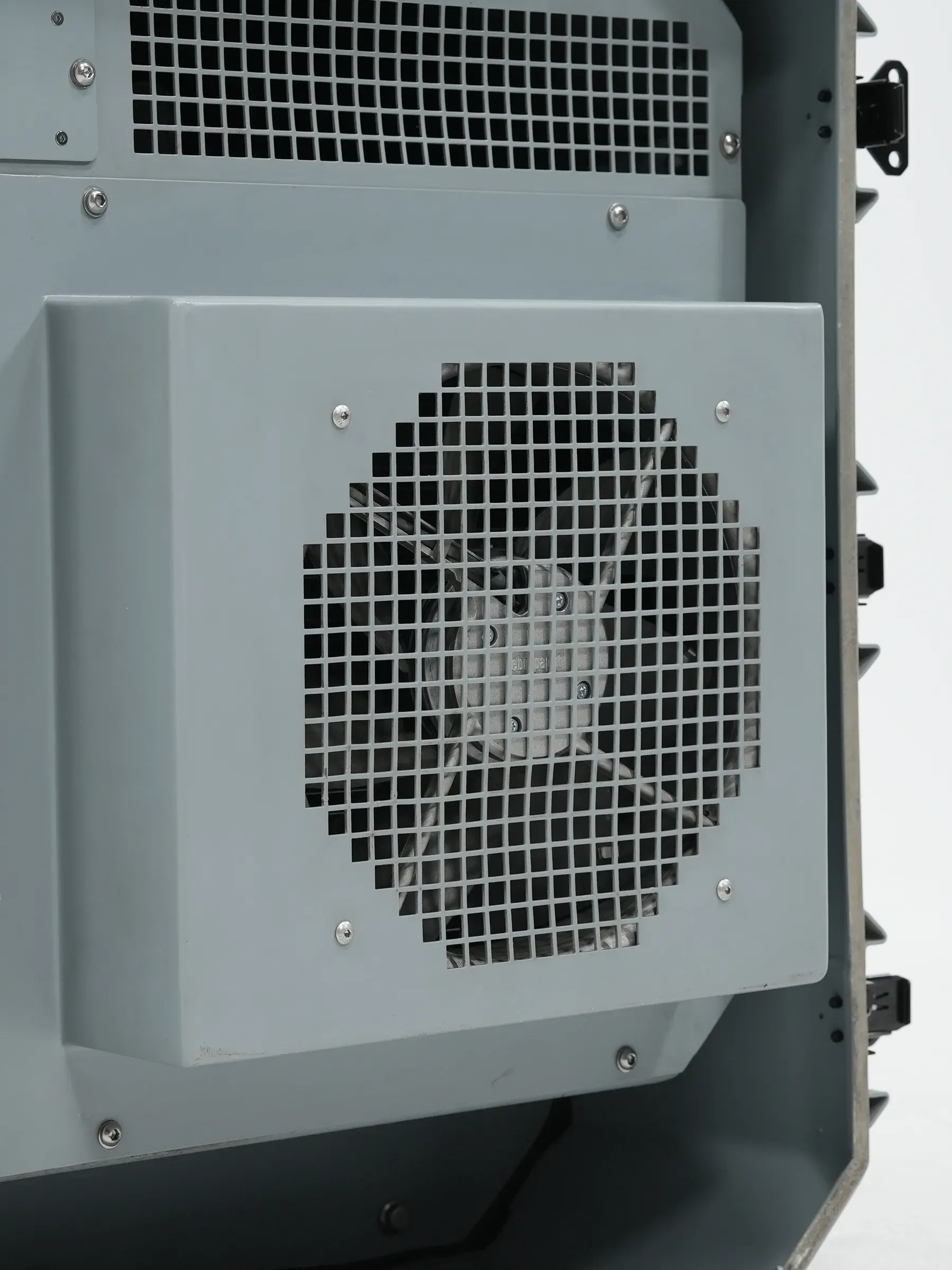
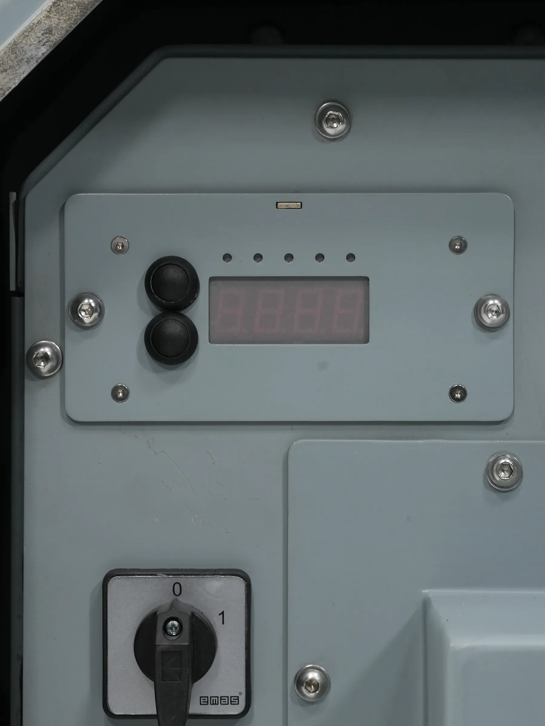
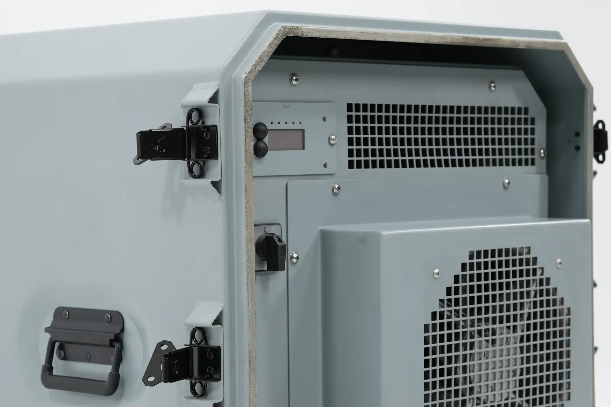

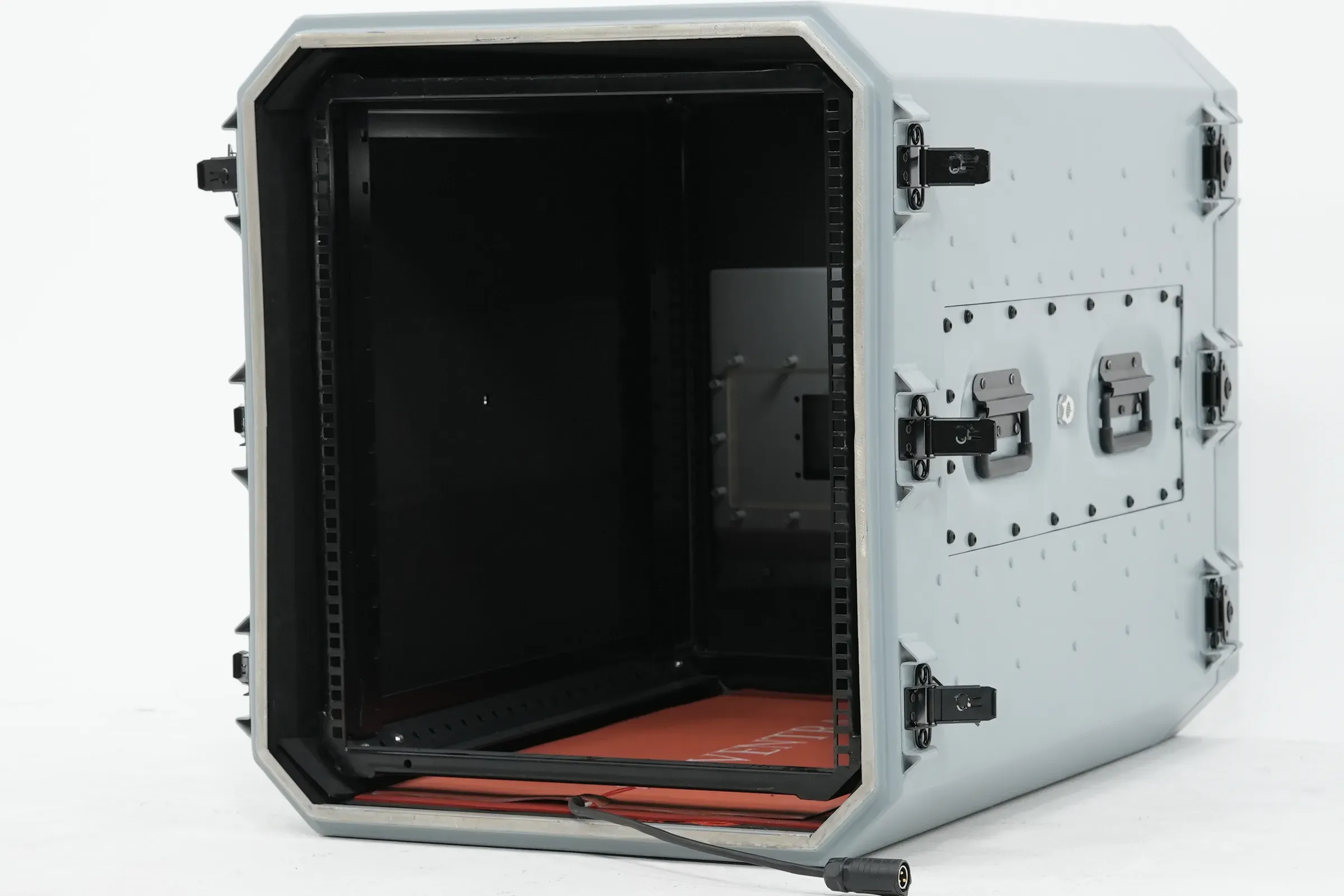
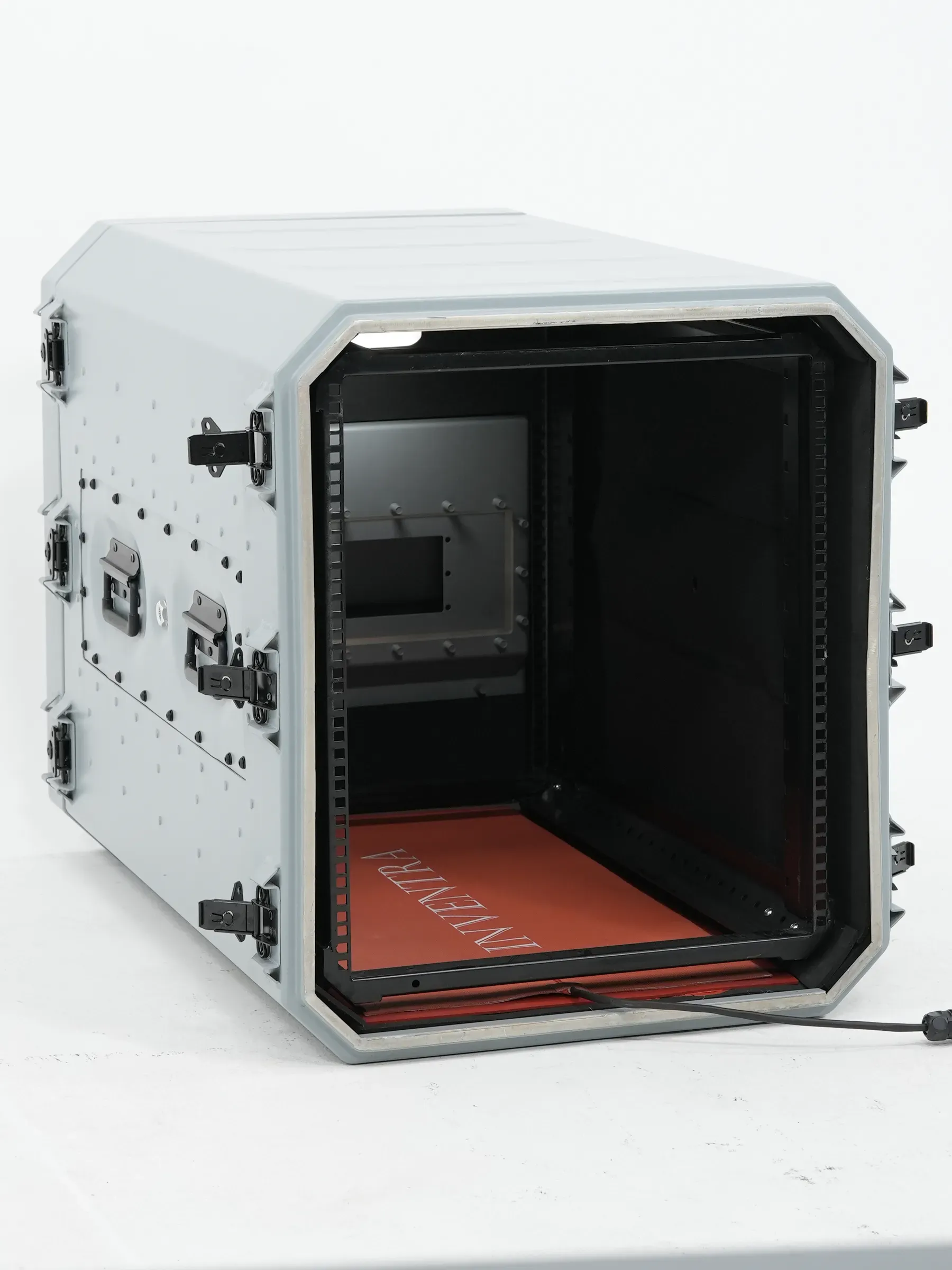
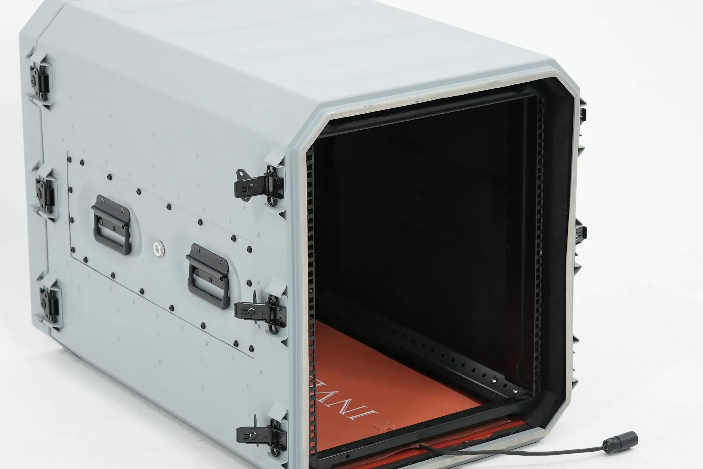
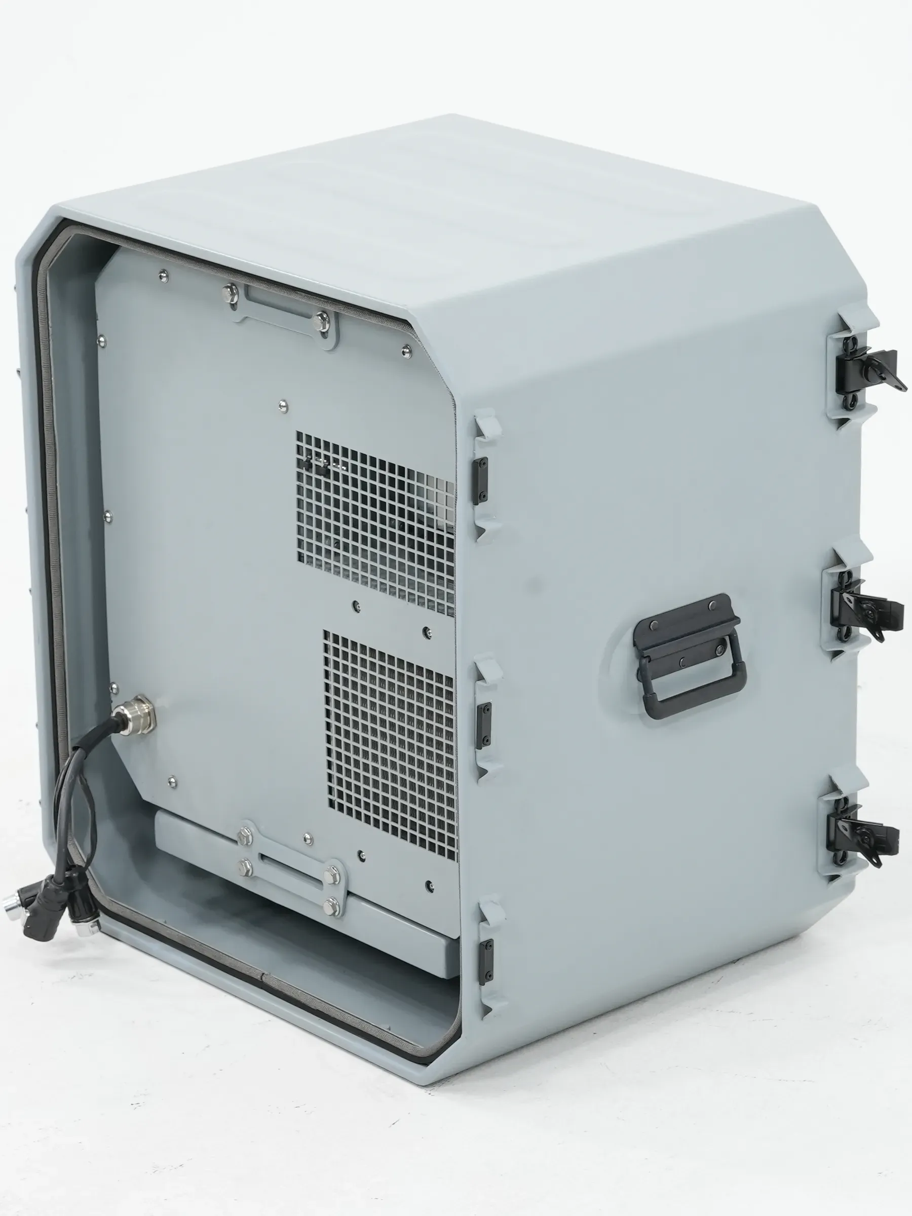
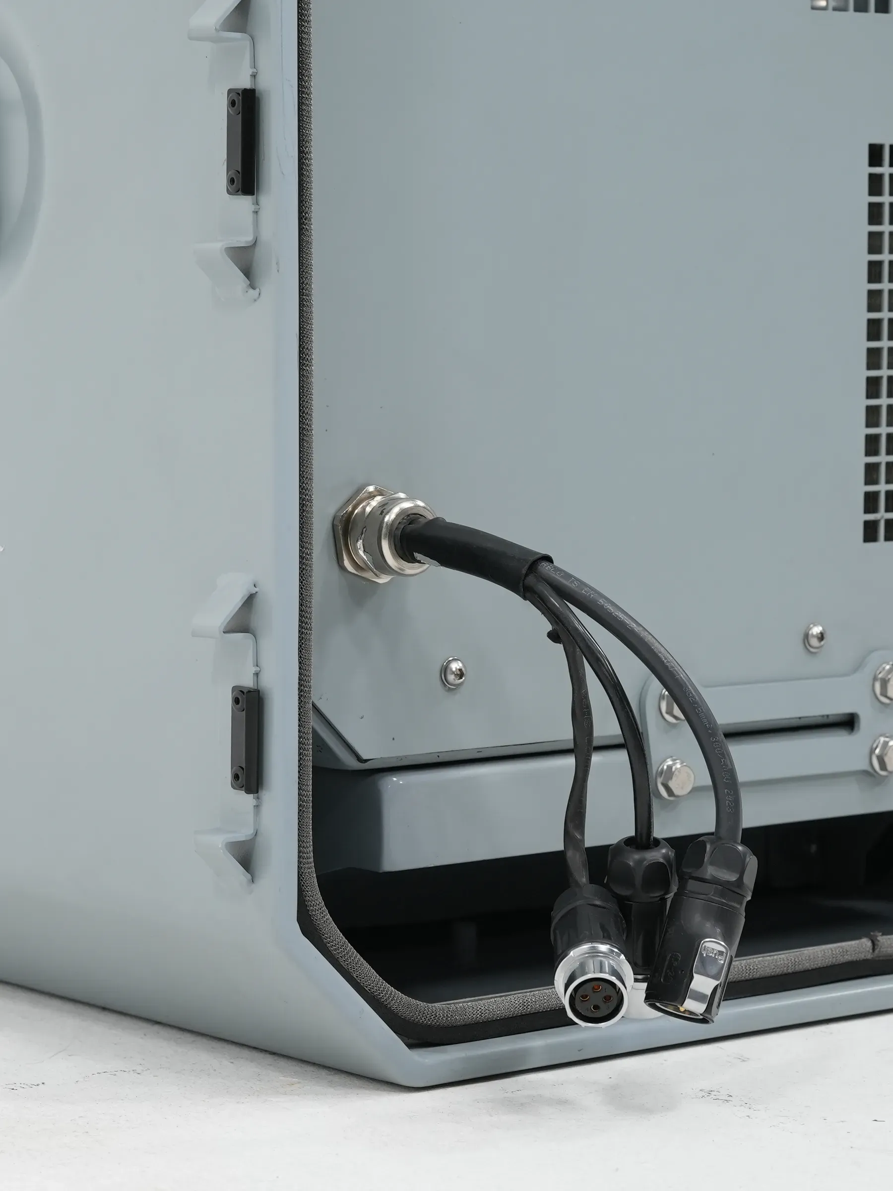
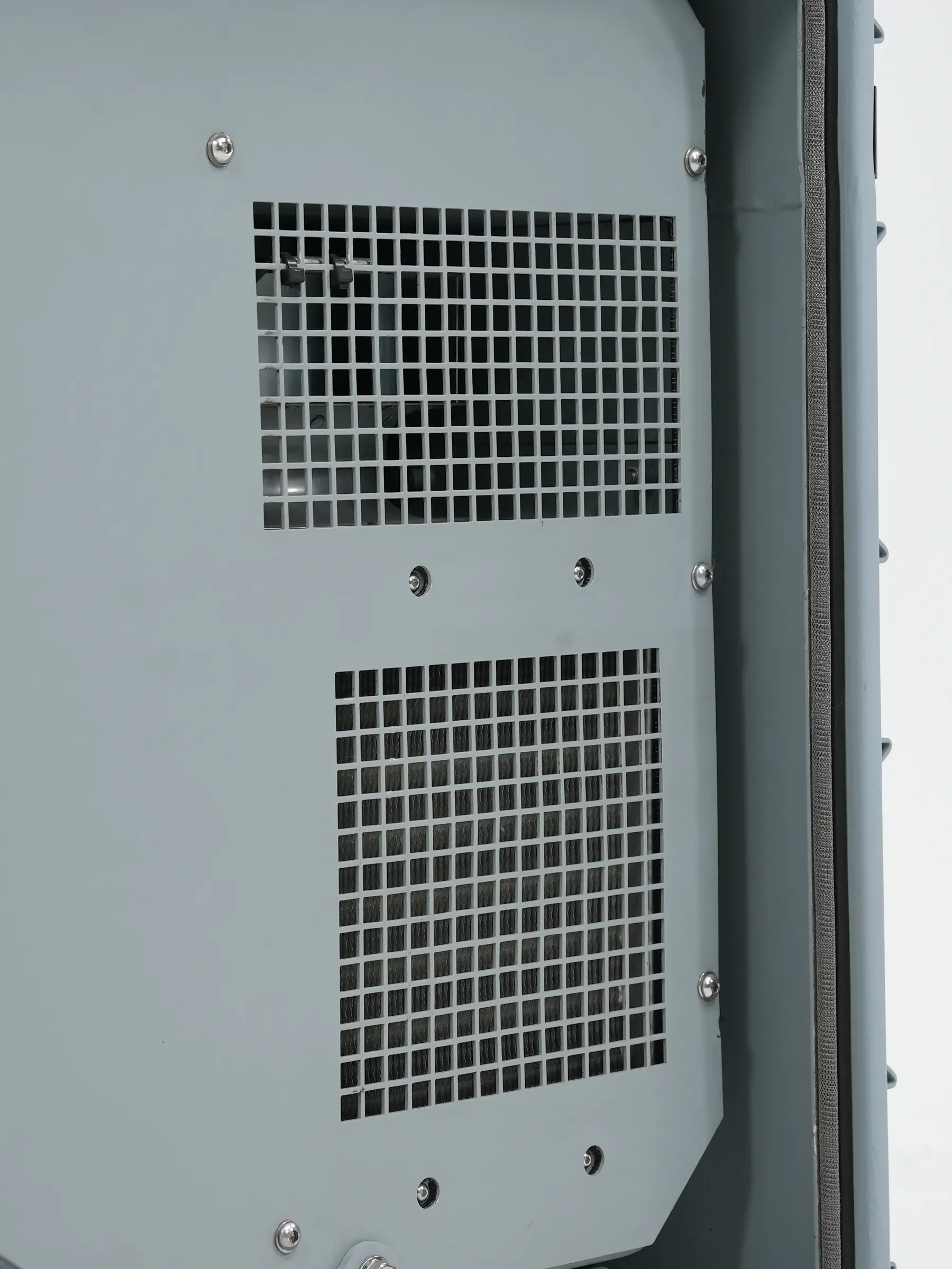
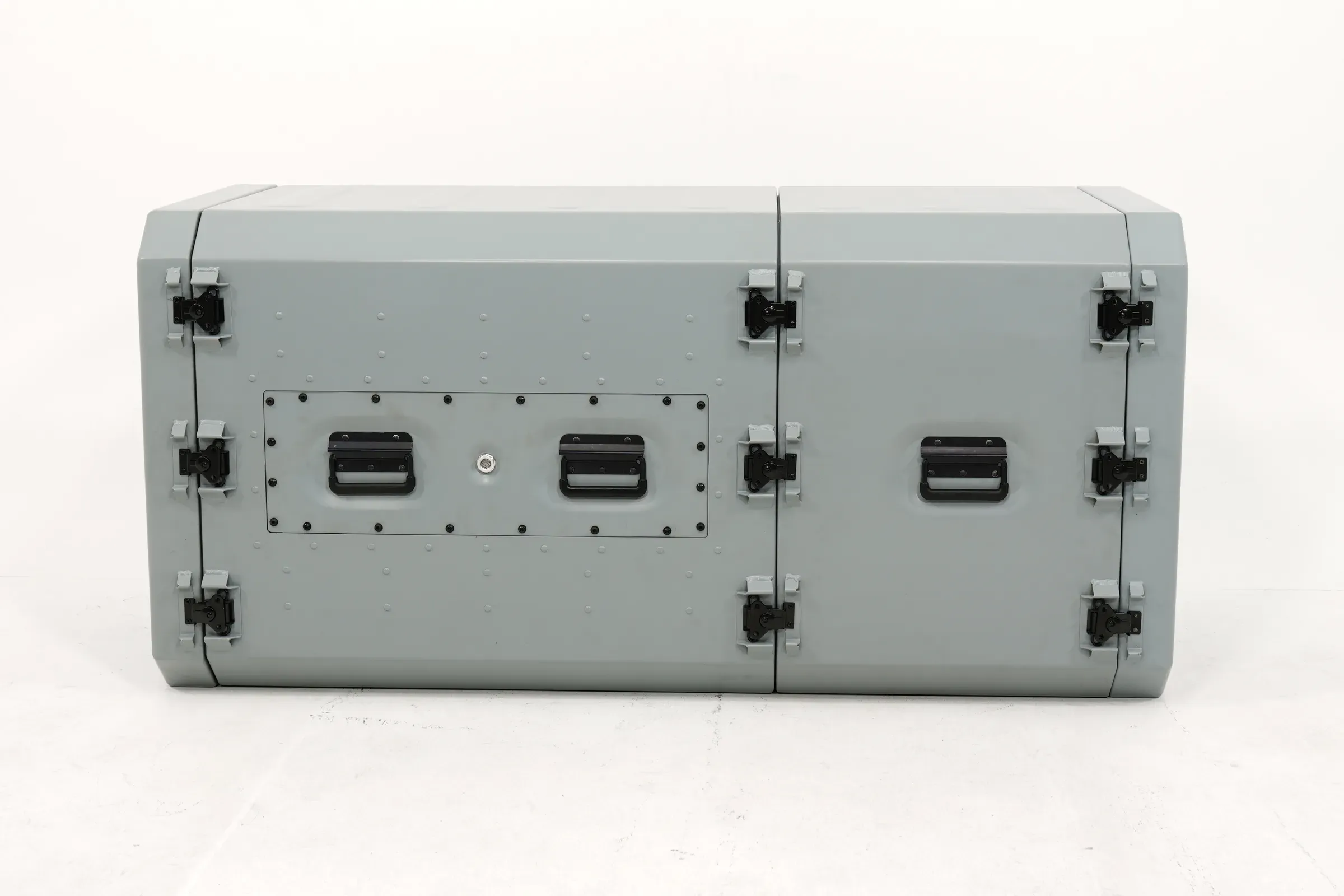
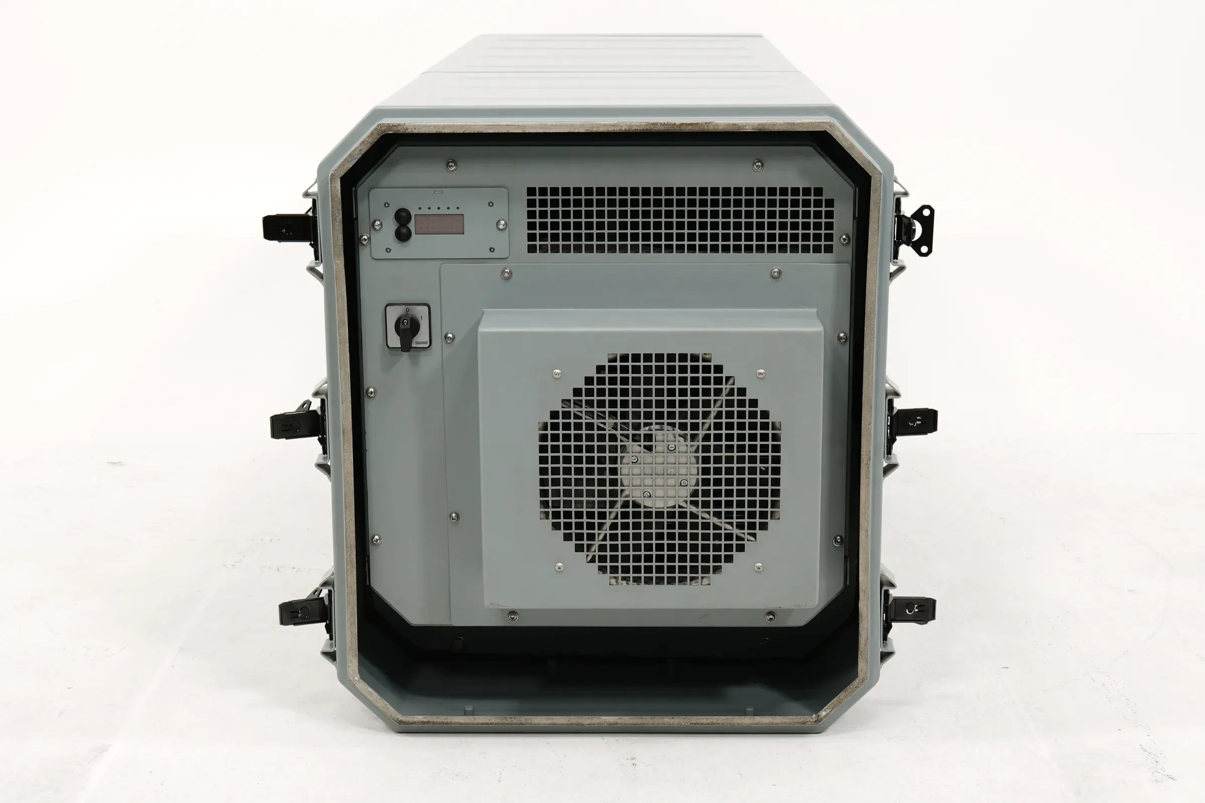
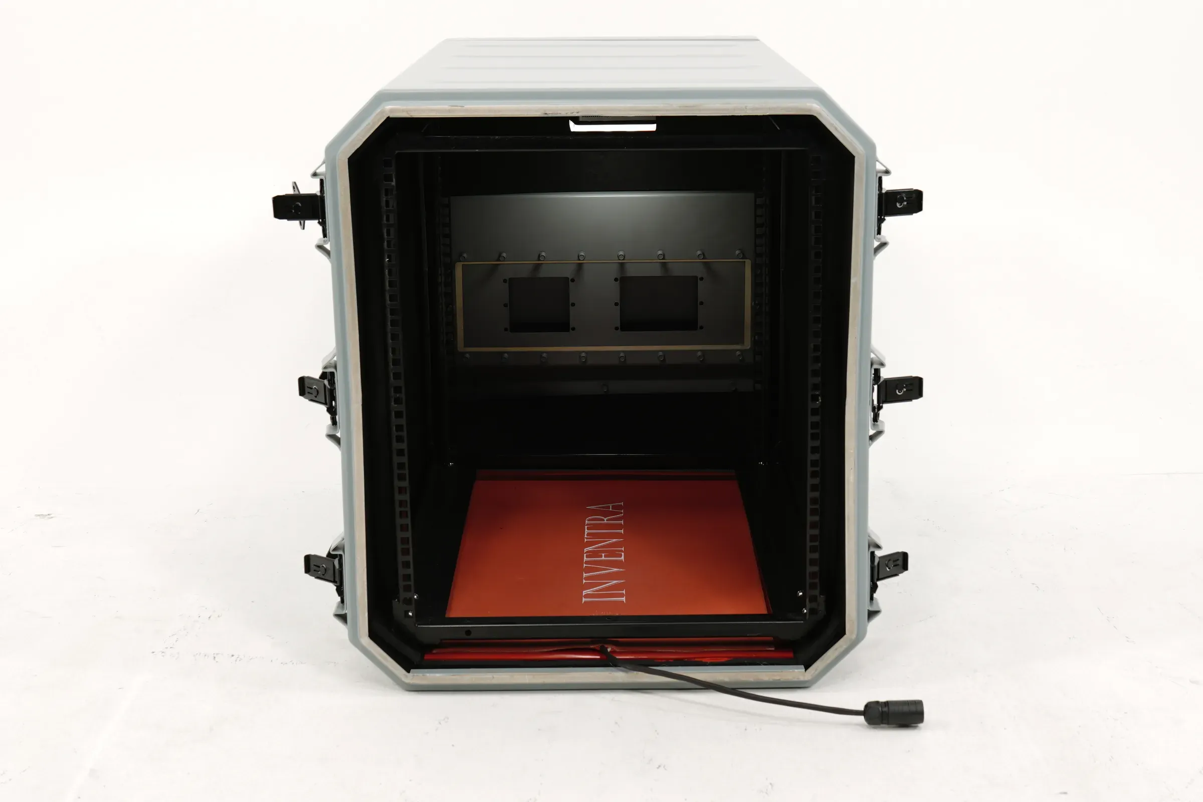
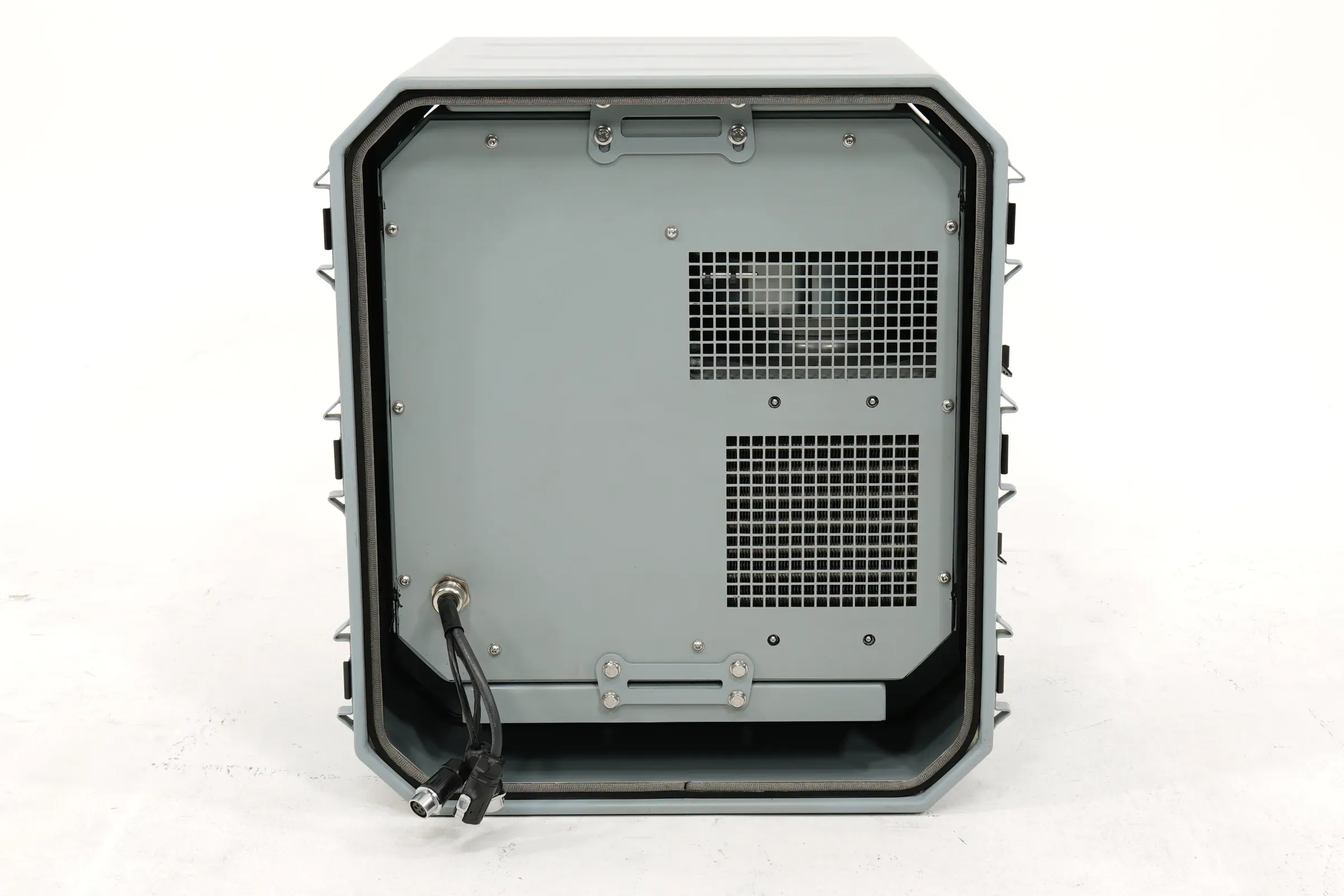
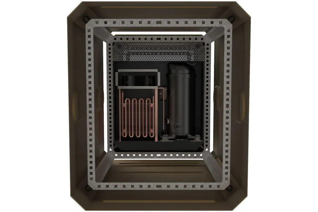
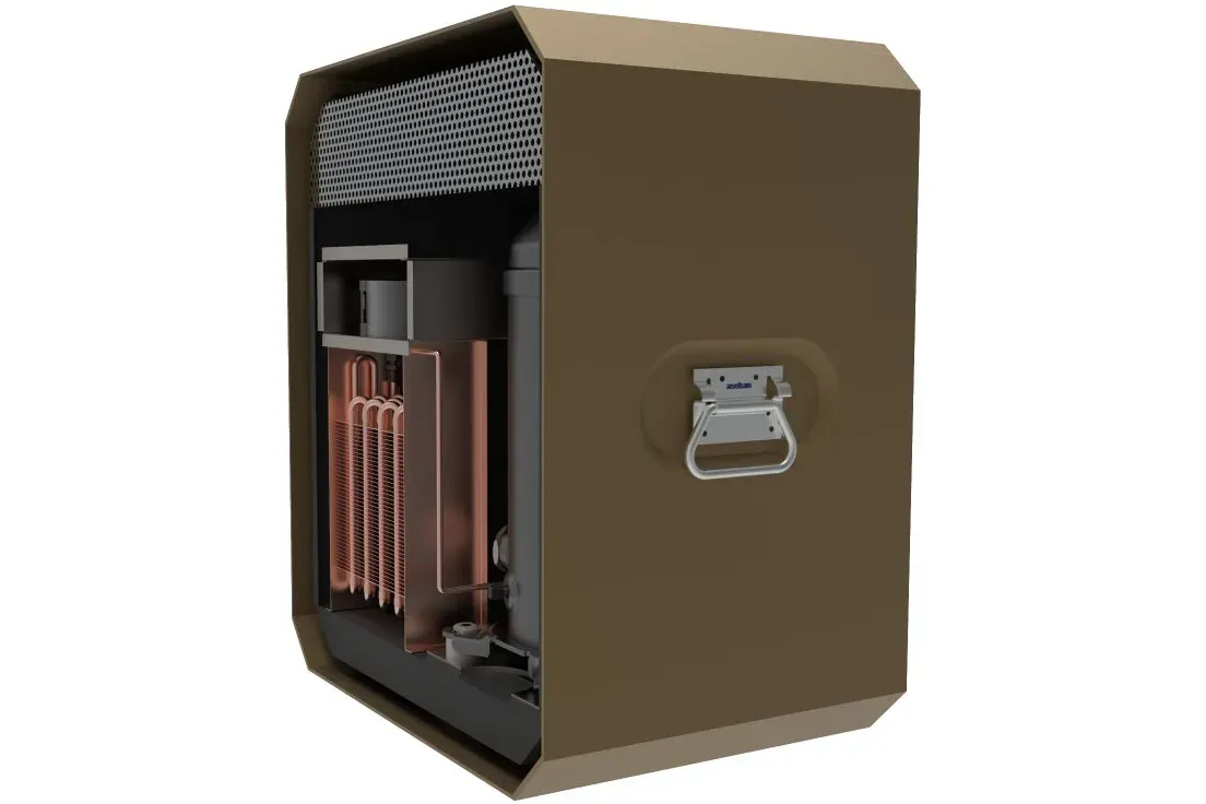
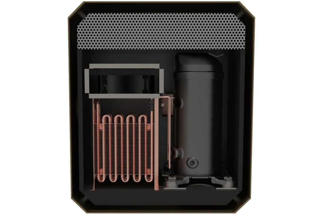
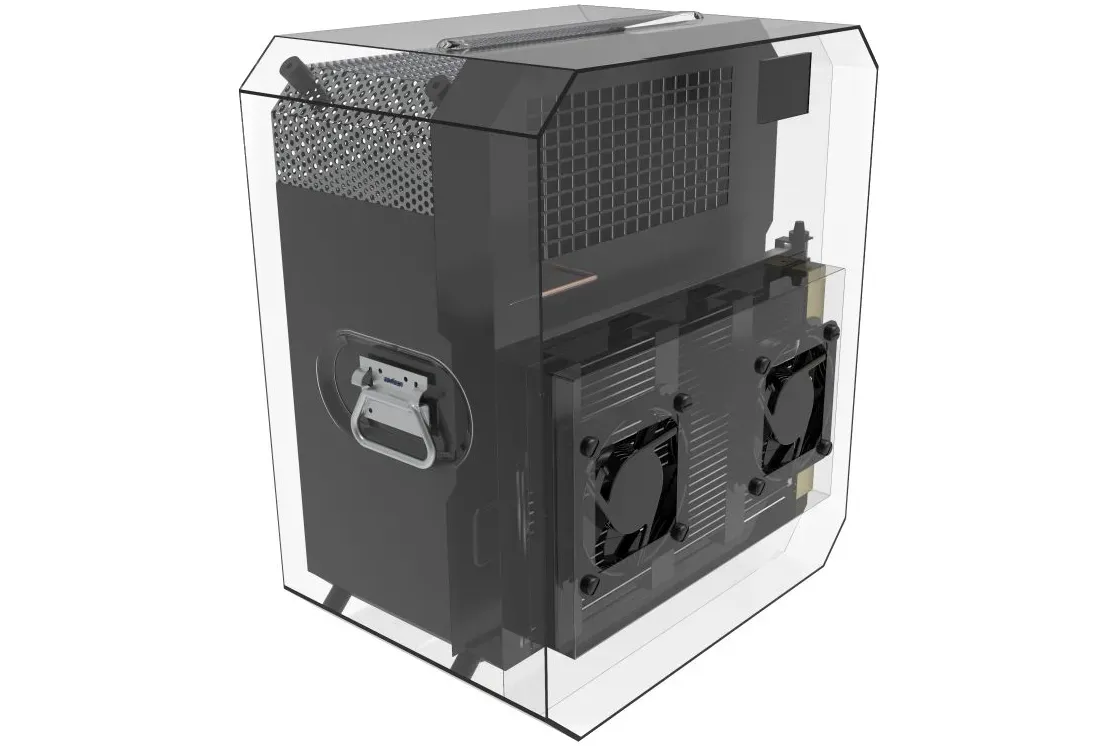
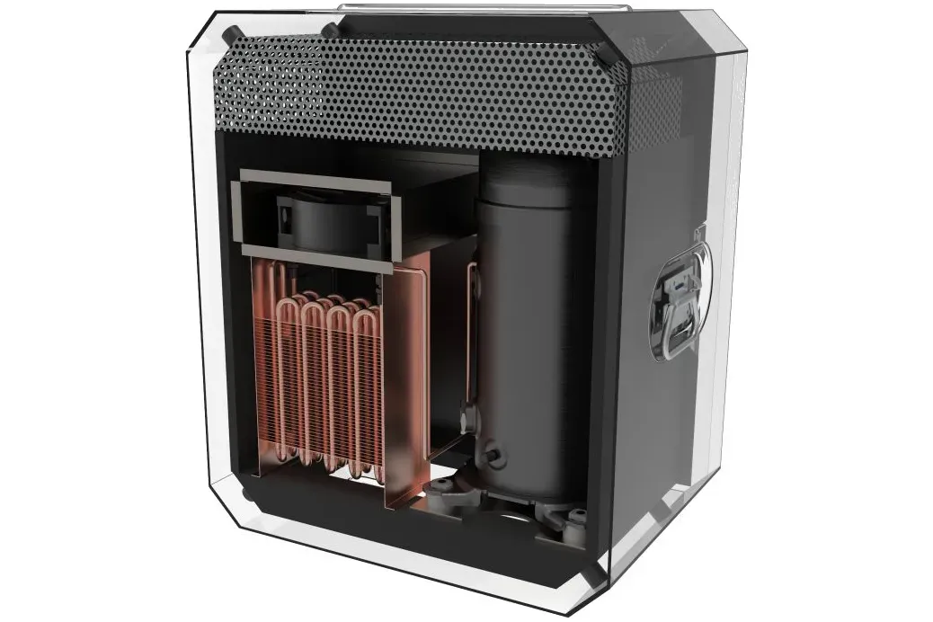
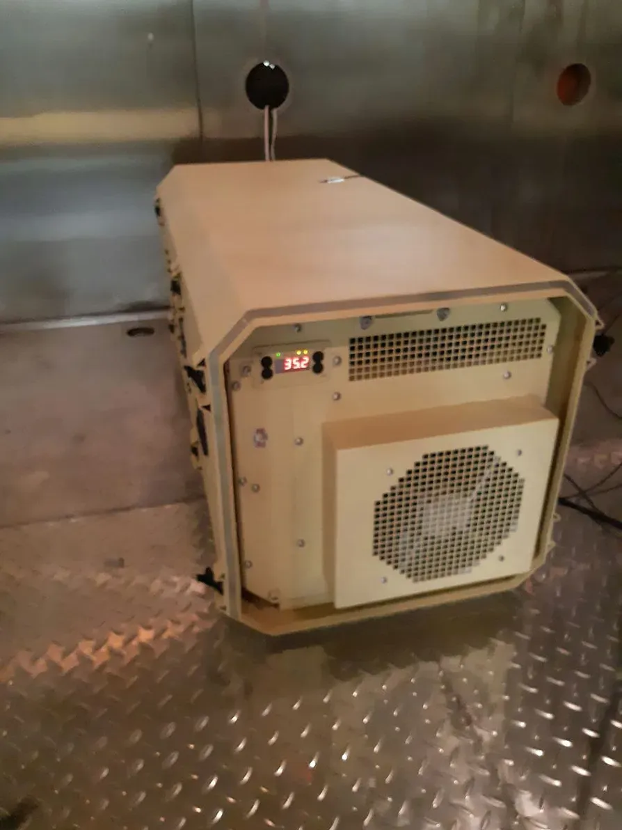
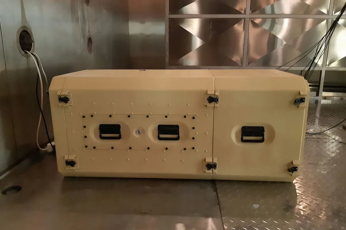
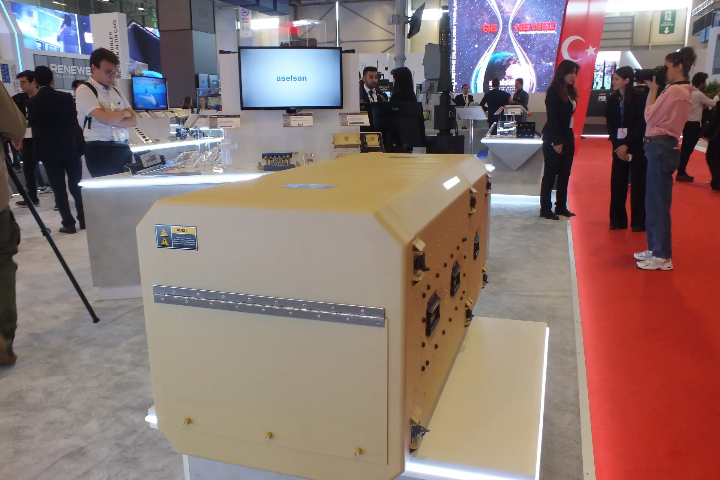
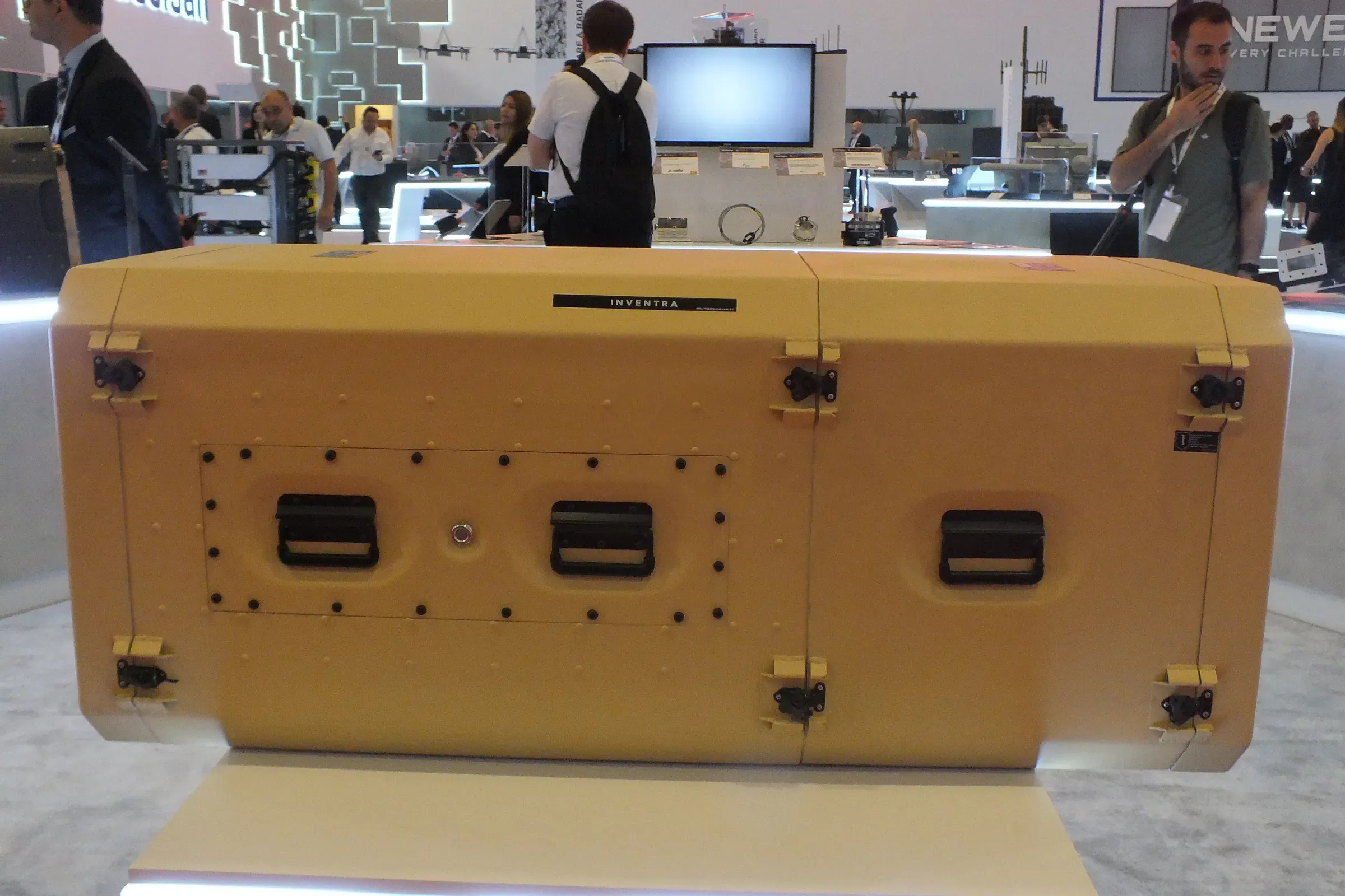
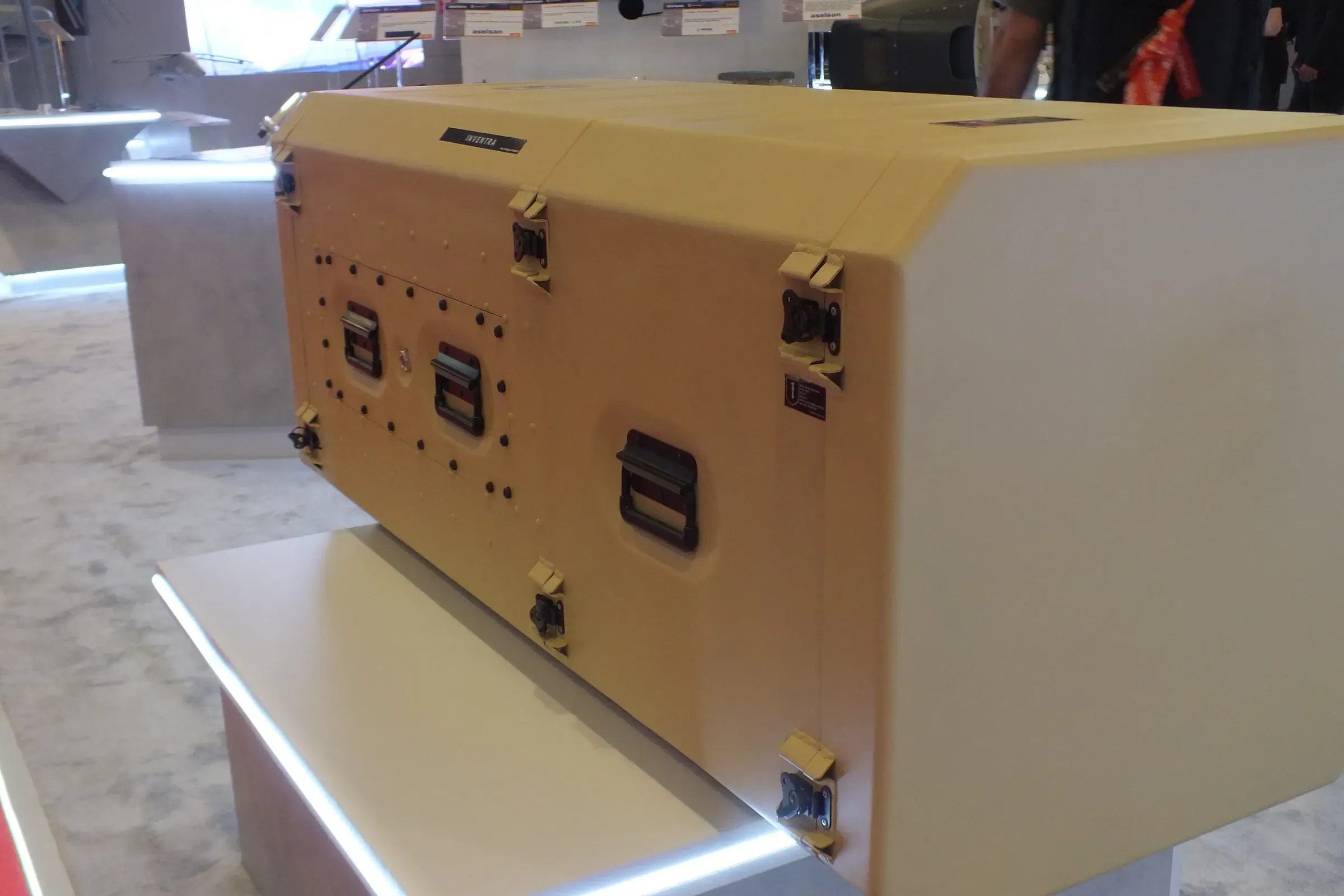
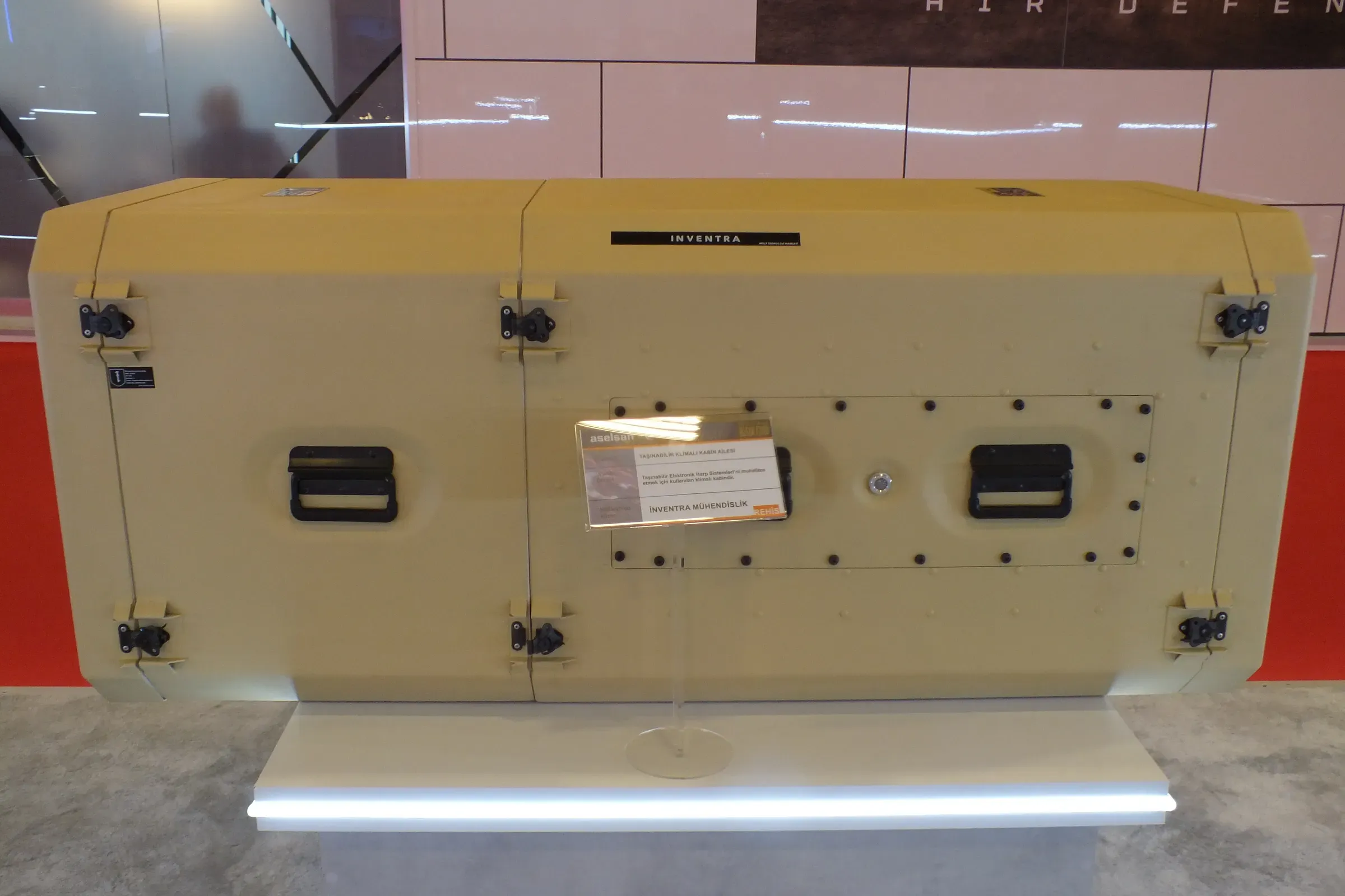
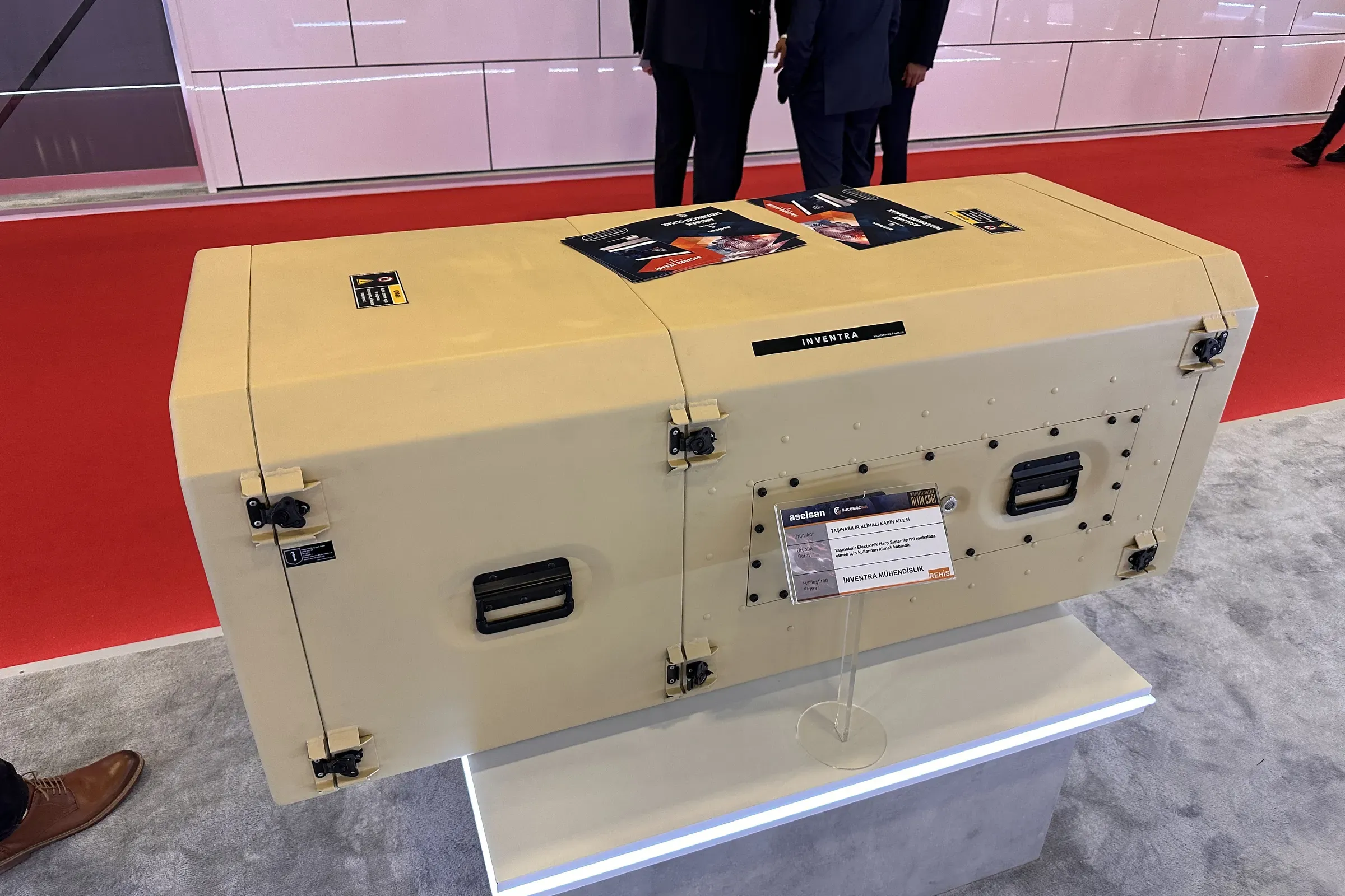
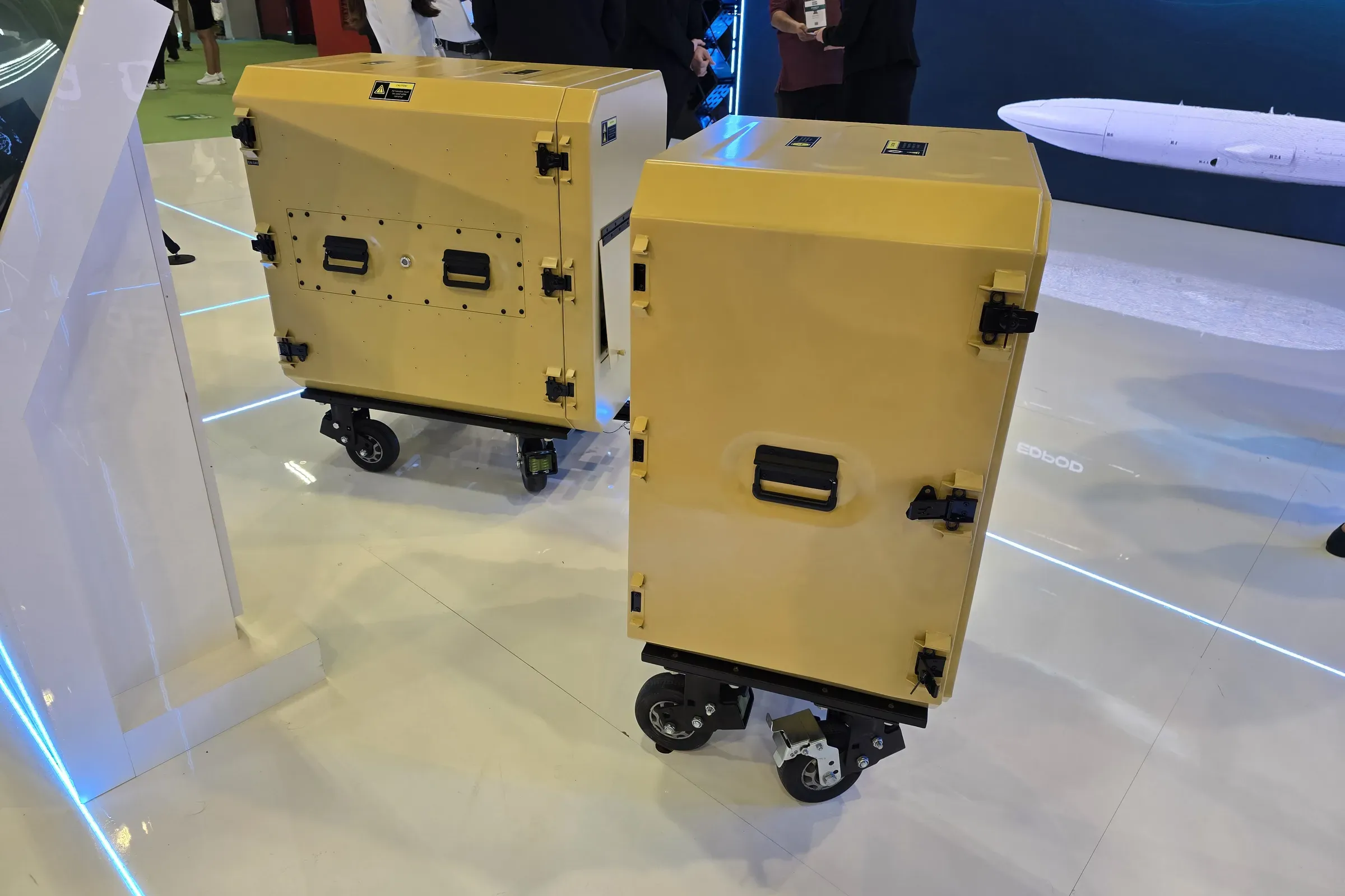
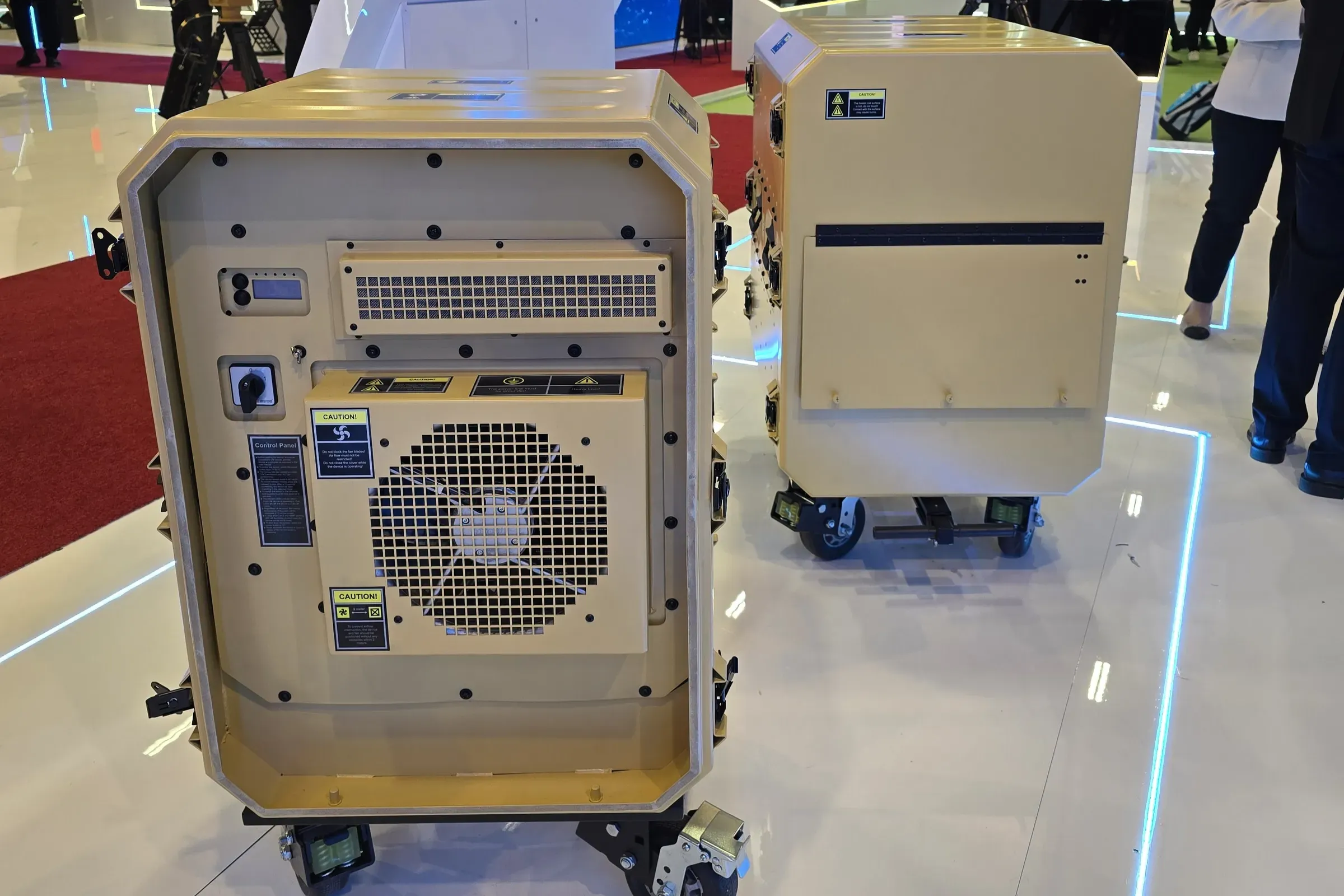
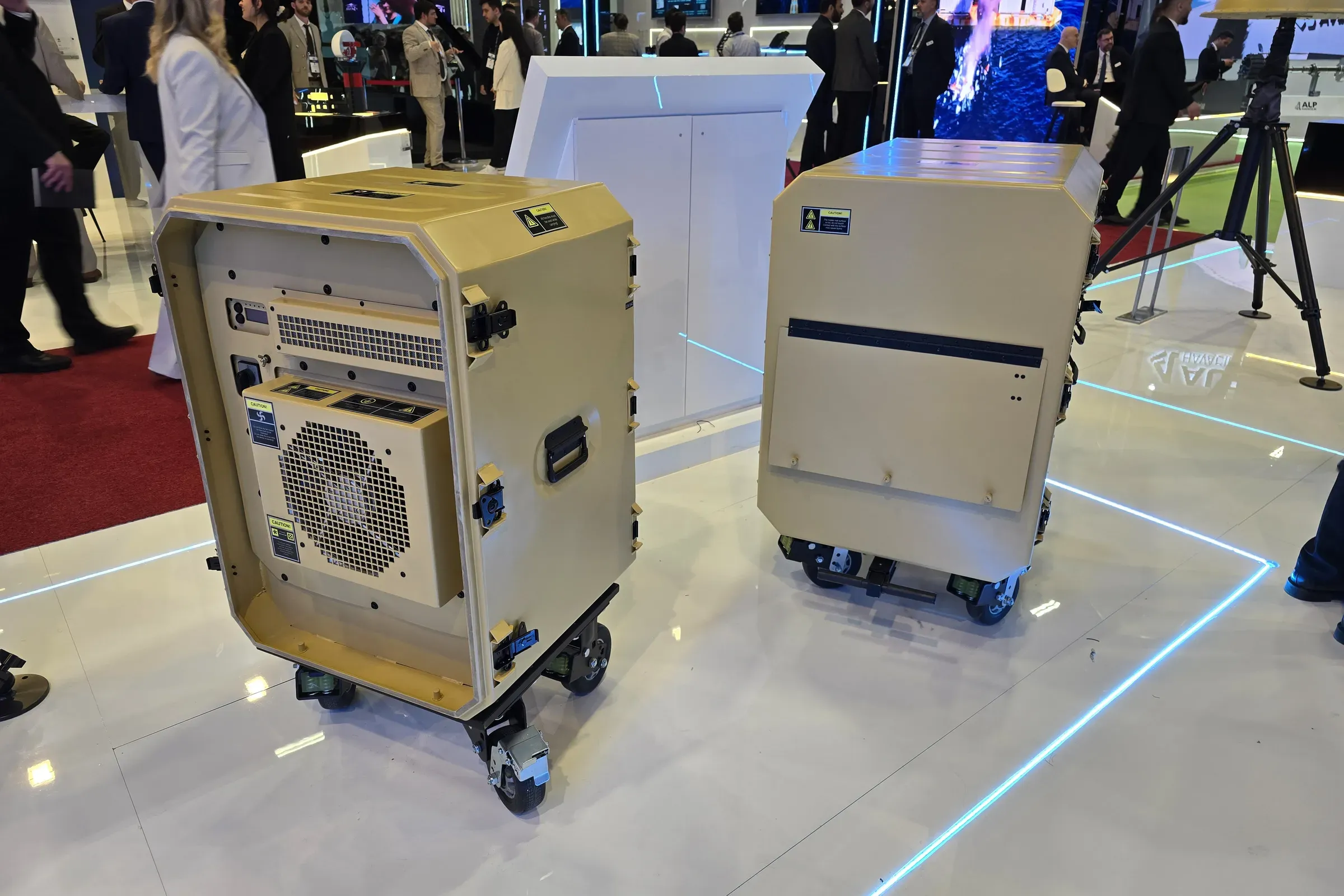
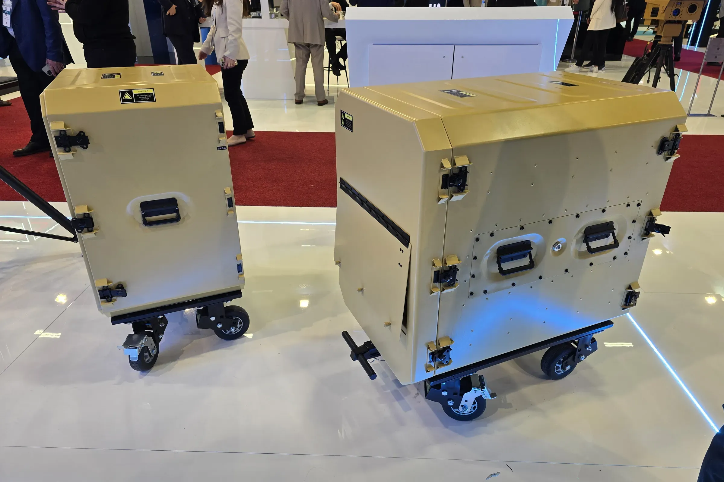
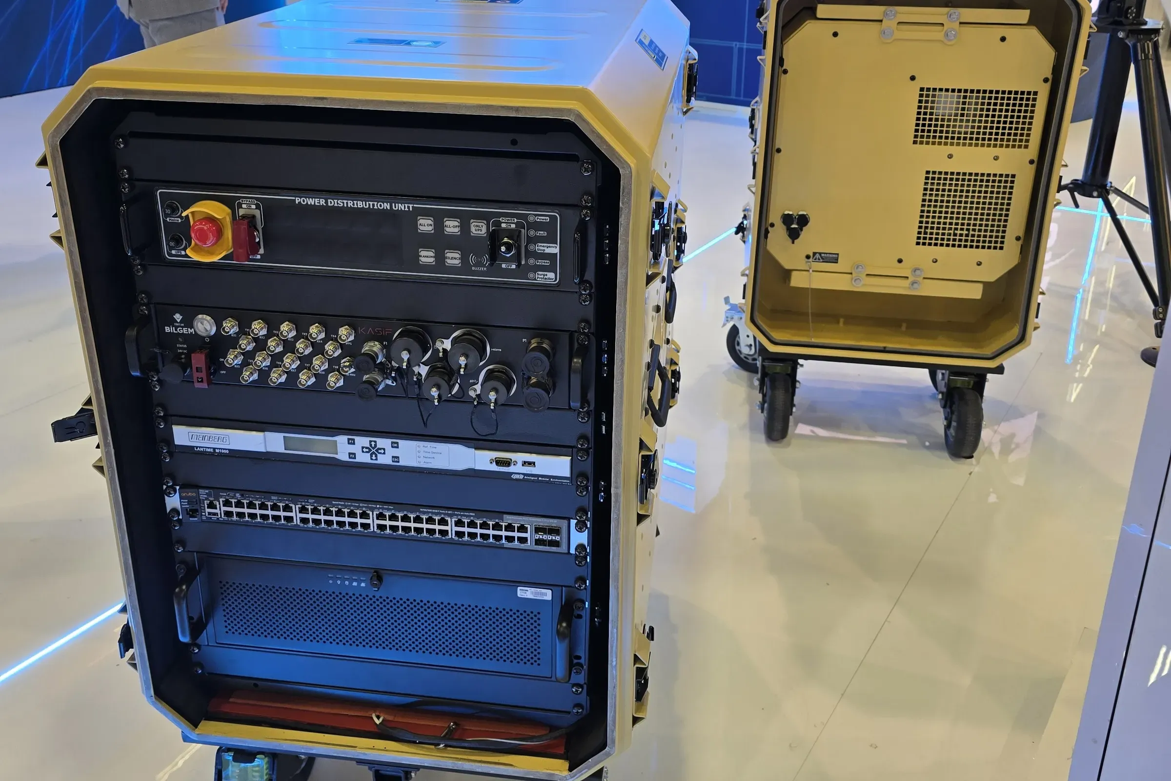
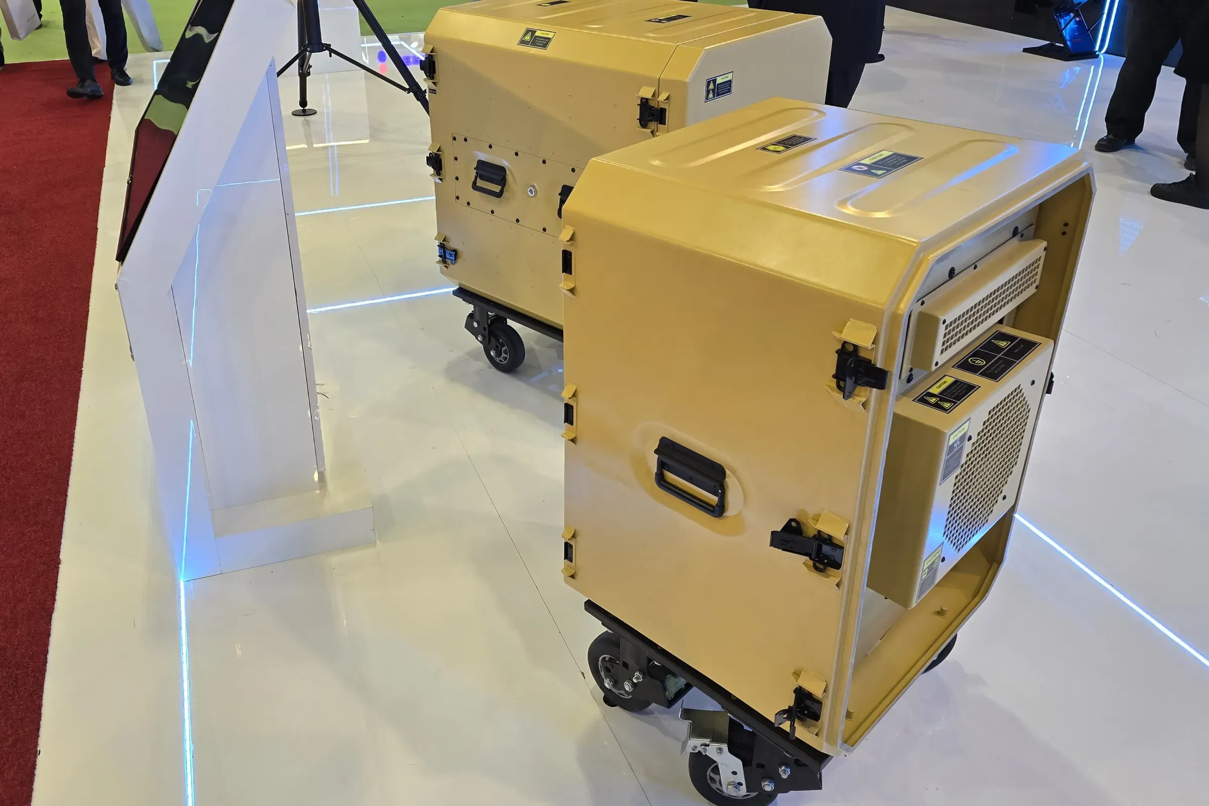
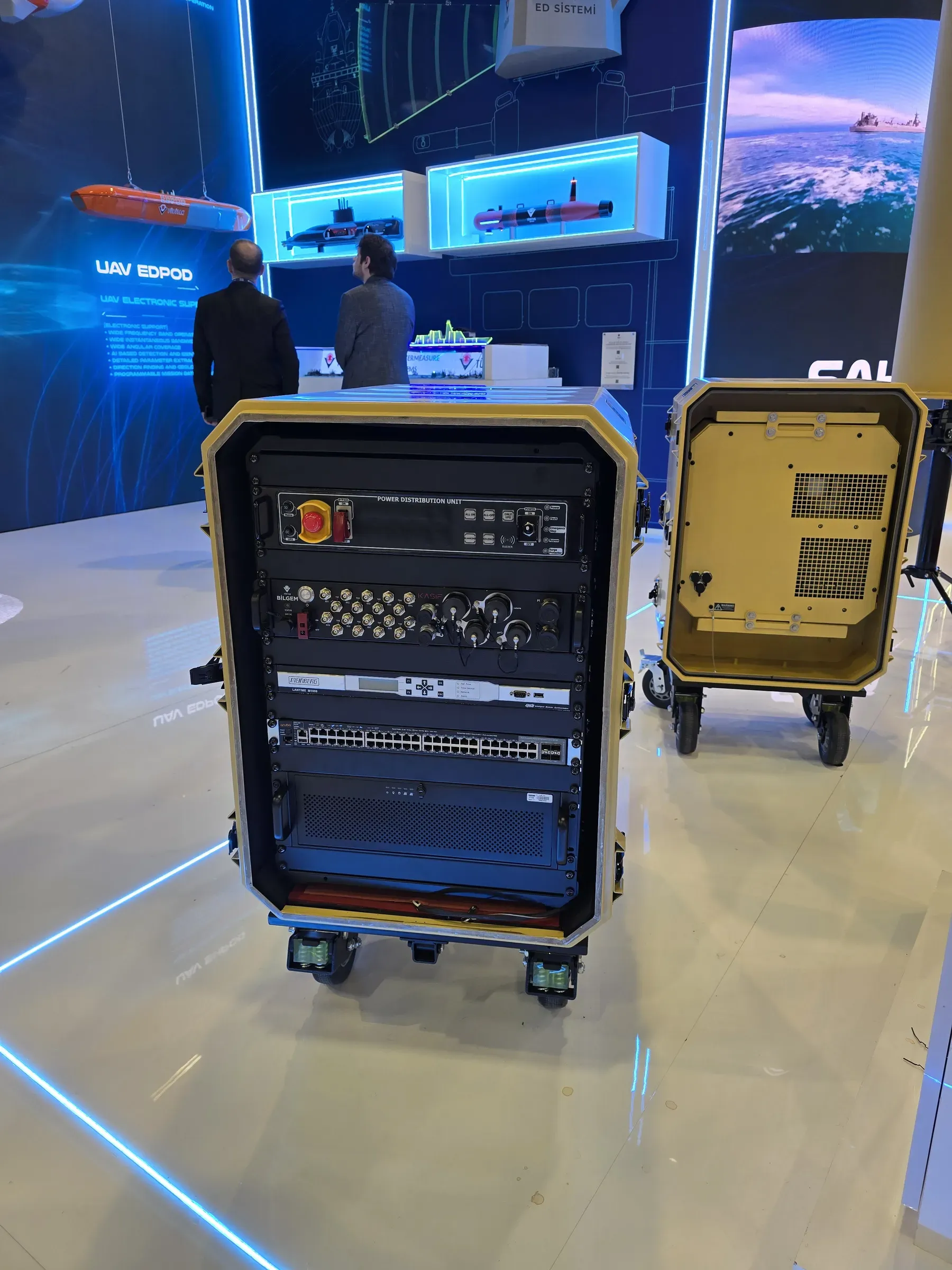
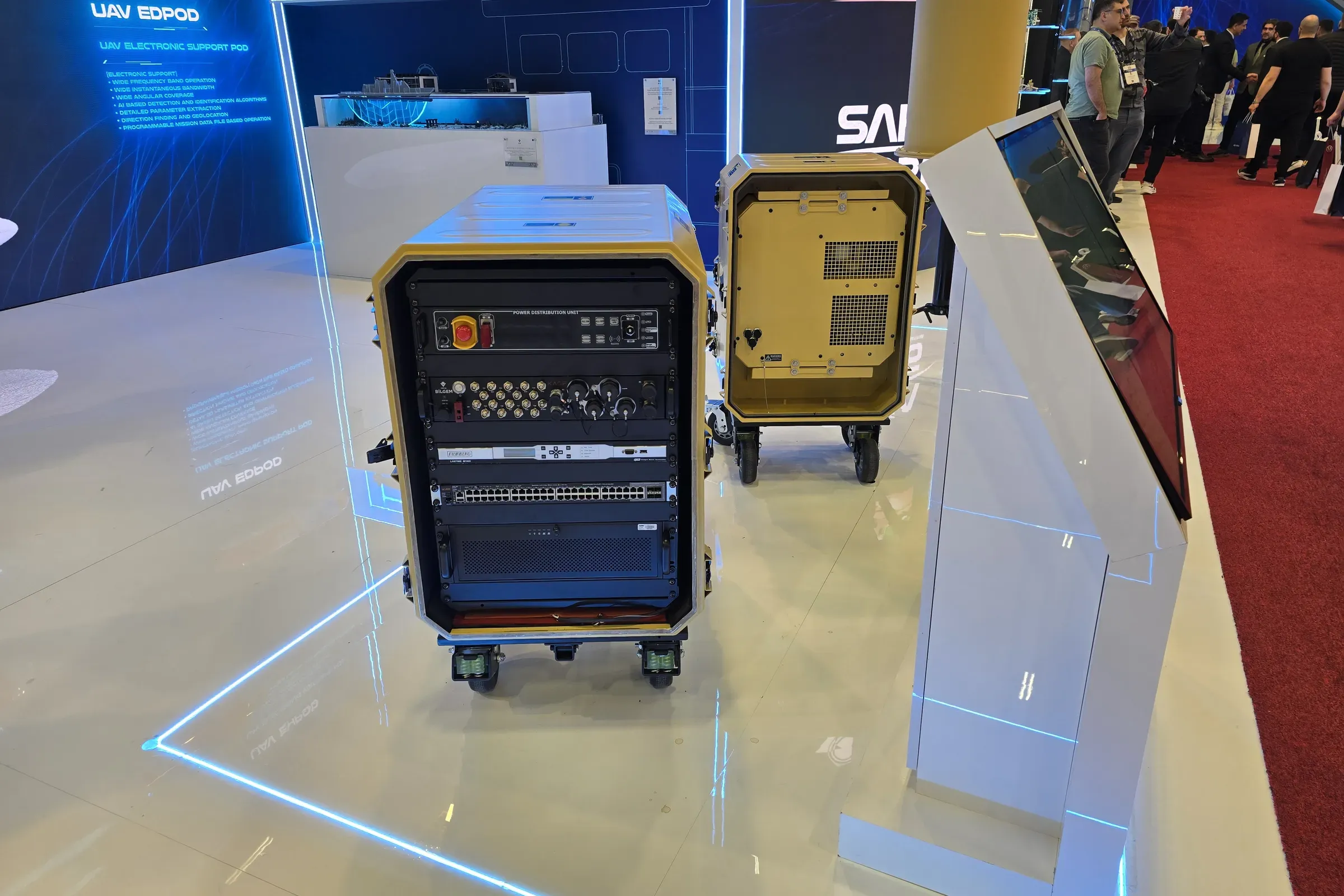
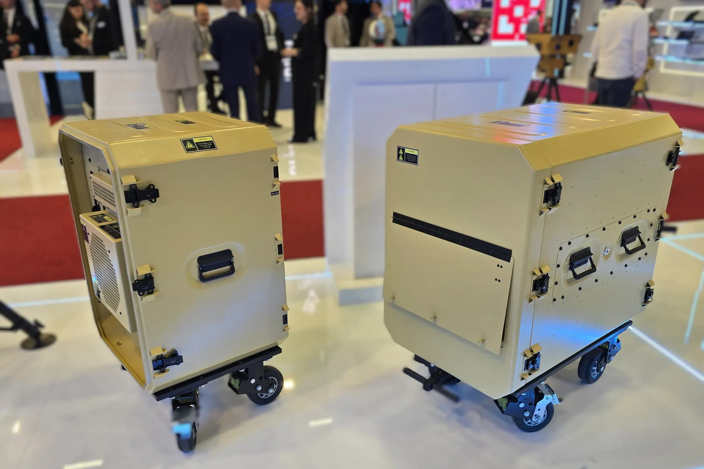
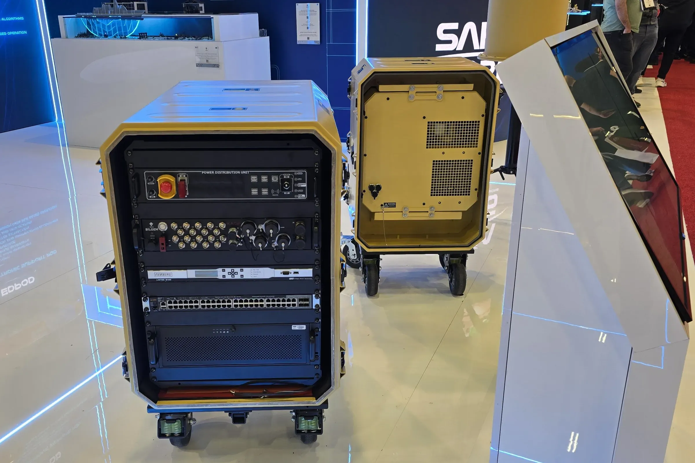
Select a frame to open it at full size.
Configurations
| Part Number | Cabin HeightU | depthmm | Wheel Type |
|---|---|---|---|
| ACP20-10U-610-WDLYStandard | 10 | 610 | Wheel Dolly |
| ACP20-10U-610-FXWH | 10 | 610 | Fixed Wheels |
Options
- H075Heating Power750 WTypeLow profile silicone mat
- H150Heating Power1.500 WTypeLow profile silicone mat
- PRVLPressure Relief Valve
- STPHStowage Pouch
- SHTRShelf Trayordered separately
- LG##Label LanguageEN English, FR French, TR Turkish, AR Arabic, ES Spanish
Specifications
| Locking Mechanism | Butterfly Latch |
|---|---|
| EMI/EMC Shielding | Available |
| Cooling Capacity | 1.500 W |
| Cooling Type | Vapour Compression Cycle |
| Mains Voltage | 220 VAC |
|---|---|
| Mains Frequency | 50 Hz |
| Cabin Height | 10U |
|---|---|
| Chassis Depth | 610 mm |
| Wheel Type | Wheel Dolly |
| Material – Main Body | Aluminium 6061-T6 |
| Surface Finish | Electrostatic Powder Coating |
| Standard Colour | RAL 7001 Grey |
| Installation Manual | 1 × Installation Manual |
|---|
| Environmental Standard | MIL-STD-810G |
|---|---|
| High Temperature – Operational | Mtd. 501.5, Proc. II, +60 °C |
| High Temperature – Storage | Mtd. 501.5, Proc. I, +70 °C |
| Low Temperature – Operational | Mtd. 502.5, Proc. II, -32 °C |
| Low Temperature – Storage | Mtd. 502.5, Proc. I, -40 °C |
| Low Pressure – Operational | Mtd. 500.5, Proc. II, 10.500 ft |
| Low Pressure – Storage | Mtd. 500.5, Proc. I, 37.000 ft |
| Humidity | Mtd. 507.5, Proc. II, 90 % RH non-condensing at +60 °C, 10 cycles of 24 h |
| Rain | Mtd. 506.5, Proc. I, 1,7 mm/min, 18 m/s wind, 30 min per exposed face |
| Salt Fog | Mtd. 509.5, 5 % NaCl, 2 cycles of 24 h fog and 24 h drying |
| Blowing Dust | Mtd. 510.5, Proc. I |
| Blowing Sand | Mtd. 510.5, Proc. II |
| Vibration | Mtd. 514.6, Proc. I, Cat. 4 – Secured Cargo, Fig. 514.6C-3 |
| Shock | Mtd. 516.6, Proc. I, 20 g, 11 ms, 3 shocks per direction in 3 axes |
| EMI/EMC Standard | MIL-STD-461G |
|---|---|
| CE102 | Power Leads, 10 kHz – 10 MHz |
| CS101 | Power Leads, 30 Hz – 150 kHz |
| CS114 | Bulk Cable Injection, 10 kHz – 200 MHz |
| CS115 | Bulk Cable Injection, Impulse Excitation |
| CS116 | Damped Sinusoidal Transients, 10 kHz – 100 MHz |
| CS118 | Personnel Borne Electrostatic Discharge |
| RE102 | Electric Field, 10 kHz – 18 GHz |
| RS103 | Electric Field, 2 MHz – 18 GHz |
Documents
- DatasheetDownloadable — PDF, 447 KB
- User ManualOn Request
- 3D Model (STEP)On Request
- Mechanical Interface Control DocumentOn Request
- MIL-STD-810G Environmental Qualification ReportOn Request
Application Areas
Technical Discussion and Quotation
Tell us the platform and the constraint. Our engineering team answers with a configuration that fits it.