Resource CentreTechnical Documentation
Guy Wire Installation Guide
Field installation guide for the guy wires of the MMT10 and MMT20 tripod-mast systems: level and stake layout, stake pull-out capacity by soil class, rope and pre-tension, the eleven-step sequence, the acceptance checklist and a blank installation record. Six pages.
Download PDFPDF, 434 KB
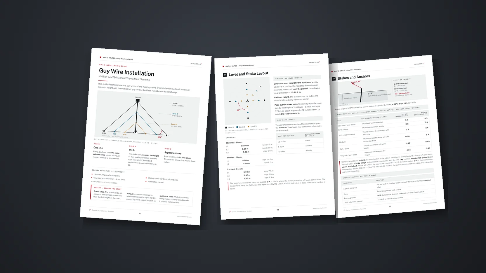
This guide describes how the guy wires of the mast systems are installed in the field. Whatever the mast height and the number of guy levels, the three rules below do not change.
Every guy level uses the same azimuth lines. Levels are never rotated relative to one another.
The stake radius equals the height of that level's guy collar, so every rope runs at 45°. Permitted deviation on a constrained site: p. 02.
Each level ties to its own stake. Three levels on one line means three stakes.
Power lines. The site must be no closer to an overhead power line than the full height of the mast.
Wind. Do not raise the mast in wind that makes the ropes hard to control by hand; raise it in calm air.
Exclusion zone. While the mast is being raised, nobody stands under it or in its fall direction.
Level and Stake Layout
Finding the Level Heights
Divide the mast height by the number of levels. Level 1 is at the top; the rest step down at equal intervals, measured from the ground: three levels on a 12 m mast → 12 · 8 · 4 m.
Radius = height. The stake sits as far out as the mast is tall, so every rope runs at 45°.
Pace out the stake point. Step away from the mast axis by the height of that level — a pace averages 0.75 m, so about 16 paces for 12 m. It need not be exact; the rope corrects it.
How Many Levels
The user chooses the number of levels; the table gives the minimum. Three levels may be fitted on a five-metre system as well.
| Mast Top Height H₁ | Minimum Number of Levels |
|---|---|
| Up to 5 m | 1 level |
| 5–10 m | 2 levels |
| 10–15 m | 3 levels |
Stakes and Anchors
A drive angle of 5–15° from vertical causes no loss of capacity (Ci = 1.00); at 30° it drops 23% (Ci = 0.77).
Stake Pull-Out Capacity — Ø25 mm stake, vertical, 45° pull, rope ≤50 mm off ground
| Soil | Field Identification by Hand | 610 mm Embedment, kN | 915 mm Embedment, kN |
|---|---|---|---|
| Very hard / very dense | Thumbnail barely indents it | 6.0 | 11.1 |
| Hard / dense | Thumbnail indents it readily | 3.8 | 7.1 |
| Stiff / medium dense | Thumb indents it, penetrates with difficulty | 1.9 | 3.6 |
| Medium | Thumb penetrates a few cm with moderate effort | 0.96 | 1.8 |
| Soft / loose | Thumb penetrates a few cm easily | 0.48 | 0.89 |
| Very soft / very loose | Squeezes out between the fingers | 0.24 | 0.44 |
Ground That Will Not Take a Stake
| Condition | Solution |
|---|---|
| Asphalt, concrete | Anchor bolt, or a ballast block — attach the rope at the block's bottom edge |
| Rock | Expanding wedge rock anchor |
| Frozen ground | Drill, do not drive. A driven stake will not enter frozen gravel |
| Soft, saturated ground | Duckbill or helical screw anchor |
Installation Sequence
The sequence is written for a single operator. All guys are connected with the mast retracted; the mast is then extended with the guys attached.
Take up the rope slack by hand; straight, but not tensioned.
Mark each rope with a pencil where it enters the tensioner.
Tension each rope until the mark travels 10 cm past the tensioner — about half a hand span. The same on all four.
The tensioner has no thread; the rope is tensioned by pulling it by hand. Do not put your weight on it — on a small mast the real danger is over-tensioning.
10 cm is about 1% of the taut rope length at the middle level — what polyester rope stretches at one tenth of its breaking load. What matters is not a force but that the four ropes match: if they do, the mast stands plumb by itself; if it leans, the stake point is wrong.
Set up the tripod, spread the legs equally and bring the top plate level by eye.
Set the four guy directions, roughly 90° apart. Each opposing pair must line up with the mast on one straight line — check by eye. If the prevailing wind is known, set one line into it.
Pace out the stake points: on each line, step out from the mast axis by the height of that level. A pace averages 0.75 m.
Drive the stakes — 5–15° from vertical, leaning away from the pull, all to the same depth.
Fit the guy collars. The Level 1 collar goes immediately below the payload adapter.
Lay out the ropes and tie each to its own stake. Run the rope through the tensioner with slack; check that no rope is fouled on another or on a tripod leg.
Extend the mast from the bottom section upwards. Take up the rope slack by hand, do not tension.
Tension from the bottom up: Level 3 first, then Level 2, Level 1 last. At each level, one opposing pair then the other. Work in three passes; by the last pass all four marks reach 10 cm.
After each pass check the plumb. Tensioning an upper level slackens the ones below it; correct any lean with the opposing pair in that plane only.
Confirm the plumb. With the four ropes equally tensioned and the stakes at equal distance, the mast is plumb by construction. If it still looks off, correct the stake point, not the tension. On critical systems, verify with a plumb laser.
Check that all four marks sit the same distance past the tensioner; the spare rope tails should match too — if one differs clearly, that stake is misplaced. Coil and tie off the spare tail, then fill in the record.
Acceptance Checklist
Once the mast is plumb and before the system is handed over, verify each of the seven items below in turn. If any single item fails, the installation is not complete.
All four rope marks 10 cm past the tensioner — the same on each
Each opposing pair of stakes in line with the mast
Roughly 90° between the two pairs of stakes
All levels on the same azimuth lines
Mast plumb — sighted by eye from two points
All four ropes tensioned by hand with equal force
Thimble and stainless rope clip at every loop
- Levels are never rotated relative to one another. All levels use the same azimuth lines.
- The levels on one line are never gathered on a single stake — the load on that stake multiplies by the number of levels and pulls it out of the ground.
- Ropes are never over-tensioned. Over-tensioning reduces the load capacity of the mast.
- A stake is never driven perpendicular to the rope. It stays within 5–15° of vertical, leaning away from the pull.
Check the stake heads by hand every day; drive any that has loosened, or move it. After rainfall stake capacity is halved — check the stakes again. Synthetic rope beds in over the first few days; check the tension every 3–7 days. Pre-tension is defined at the temperature of assembly — readjust it whenever the temperature changes by more than ±20 °C. After high wind, hail or snow loading, fully inspect the stakes, the rope terminations and the plumb of the mast.
Installation Record
Fill this in at every installation; one copy stays with the system. The level heights and stake radii are read from this record.
Level Heights and Radii — as measured
| Level | Collar Height h, m | Stake Radius R, m |
|---|---|---|
| Level 1 | ||
| Level 2 | ||
| Level 3 |
Stakes and Pull Test — per line
| Line | Soil Class | Embedment Depth, mm |
|---|---|---|
| Line A | ||
| Line B | ||
| Line C | ||
| Line D |